
PLC-ES Positioning Data
- The basic controls, such as position and speed control, are executed by setting the required items.
- The special program, Positioning Program for PLC-ES, provides a tool for positioning data.
- A maximum of 30 position data can be configured for each axis.
- A position data occupies 8 WORDs of memory.
- The same structure of 8 WORDs of memory is applied to the POSCTRL instruction.
- Control Code must be 0 at the end of the position data list.
- When in operation, if the Control Code is 0, the PLC-ES terminates the series of positioning control and does NOT go onto the next item in the list.
- When a set value is written to the data register used as indirect data in the sequence program, the set value of the position data gets modified.
Positioning Data
| Offset | Item | Bit | Description |
|---|---|---|---|
| 0 | Control Pattern | 0 | Bit 0-1: Single Step Control: 00 Continuous Control: 01 |
| 0 | Control Pattern | 1 | Bit 0-1: Single Step Control: 00 Continuous Control: 01 |
| 0 | Interpolation | 2 | Bit 2-3: Non-Interpolation: 00 Main Axis: Y (Linear Interpolation): 01 Main Axis: X (Linear Interpolation): 10 |
| 0 | Interpolation | 3 | Bit 2-3: Non-Interpolation: 00 Main Axis: Y (Linear Interpolation): 01 Main Axis: X (Linear Interpolation): 10 |
| 0 | Accelerate Time | 4 | Bit 4-5: Acceleration/Deceleration Number (0 ~ 3) |
| 0 | Accelerate Time | 5 | Bit 4-5: Acceleration/Deceleration Number (0 ~ 3) |
| 0 | Decelerate Time | 6 | Bit 6-7: Acceleration/Deceleration Number (0 ~ 3) |
| 0 | Decelerate Time | 7 | Bit 6-7: Acceleration/Deceleration Number (0 ~ 3) |
| 0 | Control Codes | 8 | Refer to Control Codes table |
| 0 | Control Codes | 9 | Refer to Control Codes table |
| 0 | Control Codes | A | Refer to Control Codes table |
| 0 | Control Codes | B | Refer to Control Codes table |
| 0 | Control Codes | C | Refer to Control Codes table |
| 0 | Control Codes | D | Refer to Control Codes table |
| 0 | Control Codes | E | Refer to Control Codes table |
| 0 | Control Codes | F | Refer to Control Codes table |
| +1 | Reserved | Reserved | Reserved |
| +2 | Dwell Time | 0 ~ 65,535ms or Indirect Data (Data Register) | |
| +3 | Reserved | Reserved | Reserved |
| +4 | Operation Speed | Low WORD | 1 ~ 100,000pps or Indirect Data (Data Register) |
| +5 | Operation Speed | High Word | |
| +6 | Target Position Address | Low Word | 1 ~ 100,000pps or Indirect Data (Data Register) |
| +7 | Target Position Address | High Word |
Control Pattern
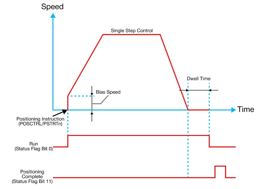
Pattern 1: Single Step Control
- The single step control executes only 1 position data.
- If Dwell time is configured, the control is terminated after the Dwell time has expired.
Pattern 2: Continuous Control
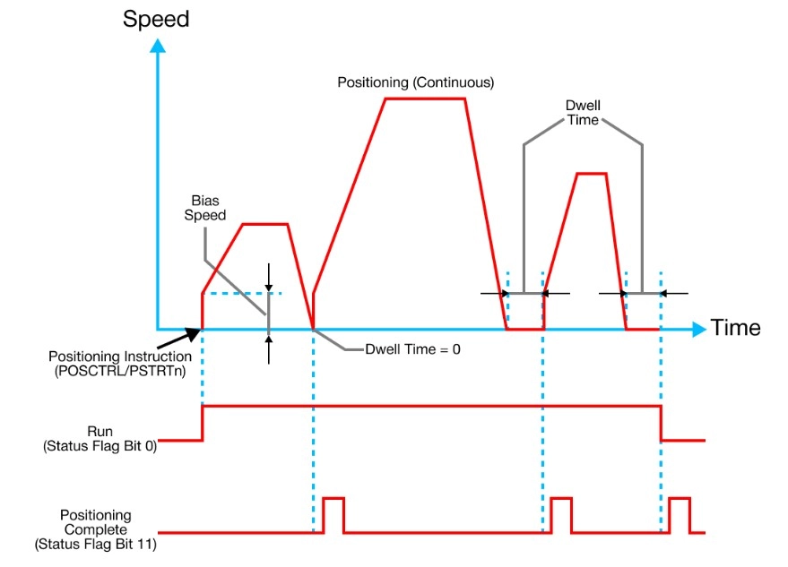
- The continuous control is used when several position data need to be executed continuously.
- The PLC-ES automatically decelerated each time the positioning is complete.
- Acceleration is then carried out after the positioning speed reaches 0 to carry out the next position data operation.
- If Dwell time is set, the acceleration is carried out after the designated time elapses.
- In continuous control operations, the next positioning number is automatically executed.
- Always set the operation pattern as Single Step in the last positioning data to terminate the continuous positioning.
- If the operation pattern is set to Continuous, the operation will continue until the operation pattern Single Step is found.
- If the Single Step operation pattern can’t be found, the positioning operation may carry out until the position data reaches 30 and terminates the operation automatically.
- If the operation pattern is set to Continuous, the operation will continue until the operation pattern Single Step is found.
- Always set the operation pattern as Single Step in the last positioning data to terminate the continuous positioning.
Interpolation
Set the main axis and sub axis for interpolation control.
Non-Interpolation:
- Used for normal single axis positioning control and does not require any additional configurations.
Main Axis Y (Sub Axis X):
- This configuration specifies the corresponding position data as interpolation and designates Y as the main axis and X as the sub axis for the interpolation operation.
Main Axis X (Sub Axis Y):
- This configuration specifies the corresponding position data as interpolation and designates X as the main axis and Y as the sub axis for the interpolation operation.
- If the main axis settings between X and Y position data don’t match, the system will select the main axis automatically.
- This is based on the moving distance.
- The axis which has a longer moving distance becomes the main axis.
- This is based on the moving distance.
- In continuous control, an interpolation axis waits until the other axis proceeds to the interpolation step.
- In this case, there is no limit on the waiting time.
- Use the Emergency Stop Request control flag to bypass the waiting status.
- In this case, there is no limit on the waiting time.
- In the interpolation operation, set values such as speed, Dwell time, and acceleration or deceleration time are taken from the main axis position data set.
- On the target position address is effectively set in the position data of the sub axis.
- The speed control command is not applicable in an interpolation operation.
- Commands for interpolation are restricted to ABS and INC.
Accelerate & Decelerate Time Number
- The acceleration and deceleration time to apply for the positioning operation is configured by selecting one of the 4 Accelerate Time/Decelerate Time values configured by this parameter.
Control Code
End Instruction
| Code (Hex.) | Code (Dec.) | Command | Function | Note |
|---|---|---|---|---|
| 00H | 0 | – | End of position data | Terminates continuous control |
Operation Command Instruction
| Code (Hex.) | Code (Dec.) | Command | Function | Note |
|---|---|---|---|---|
| 01H | 1 | ABS | End of position data | – |
| 05H | 5 | INC | Absolute Position Control | – |
| 09H | 9 | FEED | Incremental Position Control After Resetting Address | – |
| 13H | 19 | FSC | Forward Speed Control | – |
| 17H | 23 | RSC | Reverse Speed Control | – |
| 80H | 128 | NOP | No Operation | – |
Program Control Command Instruction
| Code (Hex.) | Code (Dec.) | Command | Function | Note |
|---|---|---|---|---|
| 81H | 129 | JUMP | Force to Change Next Step Number | Next step set value is stored in target position address |
| 82H | 130 | LOOP | First Step of Loop | Loop count is stored in target position address |
| 83H | 131 | LEND | Last Step of Loop | – |
| 84H | 132 | POS | Force Change Current Position Address | New address is stored in target position address |