
Instruction Parameters
Supported PLC Series
| PLC-AES | PLC-FB | PLC-ES |
|---|---|---|
| ✓ | ✓ | ✓ |
Supported Data Registers
| M | X | Y | K | L | F | T | C | S | Z | R | Q | D | @D | Constant | |
|---|---|---|---|---|---|---|---|---|---|---|---|---|---|---|---|
| S | ✓ | ✓ | ✓ | ✓ | ✓ | ✓ | ✓ | ✓ | – | ✓ | ✓ | ✓ | ✓ | ✓ | ✓ |
| D | ✓ | – | ✓ | ✓ | ✓ | – | ✓ | ✓ | – | ✓ | ✓ | ✓ | ✓ | ✓ | – |
Supported Flags
| Flag | Bit | Support |
|---|---|---|
| Error | F11.0 | ✓ |
| Zero | F11.1 | – |
| Carry | F11.2 | – |
Number of Steps
| Steps |
|---|
| 3 |
Operands
| Operand | Description |
|---|---|
| S | The first operand. Entries are WORD> data registers or constants. This is the value to search the least and most significant bit of. The signed value range is -32,768 ~ 32,767 (216). The unsigned value range is 0 ~ 65,535 (216-1). The Hexadecimal value range is H0000 ~ HFFFF. |
| D | The second operand. Entries are only WORD data registers. This stores the data register location where the data was found. This requires 2 data registers. There is an offset of +1 to the found bits if the search is successful. |
Notice
Error Flag (F11.0) Notice
The error flag, F11.0, will be ON for one scan when the address of the data register assigned by @D exceeds the range of the data register, D. The range of the data register, D, is dependent on the CPU type.
Instruction Behavior
The BSER and BSERP instructions behave as follows:
- The location of the least significant bit set (ON or 1) from the value, S, is stored in the data register, D, with a +1 offset.
- The location of the most significant bit set (ON or 1) from the value, S, is stored in the data register, D+1, with a +1 offset.
- If there is no matched data, 0 is stored in the data registers, D and D+1.
Ladder Diagram Examples
BSER

The BSER instruction searches for both the least and most significant bit set (ON or 1) in the WORD value, S. If the least significant bit is set (ON or 1), the bit location, with a +1 offset (1-based), is saved in an assigned WORD data register, D. If the most significant bit is set (ON or 1), the bit location, with a +1 offset (1-based), is saved in an assigned WORD data register, D+1.

The result of the search will be saved in the data registers, D17 and D18.


When the contact, M1.5, is powered ON (1), the instruction searches for the location of the least and most significant bits of the data register, D15.
Memory Monitor
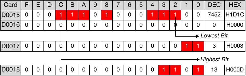
The least significant bit with a value of 1 in the data register, D15 is bit 2 (D15.2), The bit location, 2, with an offset of +1 (3), is saved in the data register, D17.
The most significant bit with the value of 1 in the data register, D15 is bit C (D15.C), or position 12. The bit location, 12, with an offset of +1 (13), is saved in the data register, D18.
BSERP

The BSERP instruction searches for both the least and most significant bit set (ON or 1) in the WORD value, S. If the least significant bit is set (ON or 1), the bit location, with a +1 offset (1-based), is saved in an assigned WORD data register, D. If the most significant bit is set (ON or 1), the bit location, with a +1 offset (1-based), is saved in an assigned WORD data register, D+1. Every time this instruction executes, it energizes the output only once.

The result of the search will be saved in the data registers, D27 and D28.


When the contact, M2.5, is powered ON (1), the instruction searches for the location of the least and most significant bits of the data register, D25.
Memory Monitor
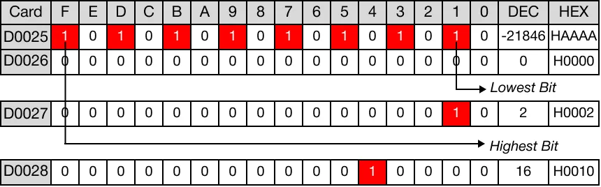
The least significant bit with a value of 1 in the data register, D25 is bit 1 (D25.1), The bit location, 1, with an offset of +1 (2), is saved in the data register, D27.
The most significant bit with the value of 1 in the data register, D25 is bit F (D15.F), or position 15. The bit location, 15, with an offset of +1 (16), is saved in the data register, D28.