Positioning for PLC-ES Special Program Control Codes
ABS (Absolute Coordinate)
- Position control by absolute coordinate is performed based on the address designated in the origin point address.
- The object moves from the start address to the target address.
- Direction of movement is determined by the sign (+ or -) and the pulse output method of the movement amount.
- Pulse Output Method – High Active Mode:
- When the movement direction is positive (+): Forward positioning.
- When the movement direction is negative (-): Backward positioning.
- Pulse Output Method – Low Active Mode:
- When the movement direction is positive (+): Backward positioning.
- When the movement direction is negative (-): Forward positioning.
- Example: If the start address is 1,000 and the target address is 5,000, the PLC-ES moves forward and stops at 5,000.
- The overall movement amount is 5,000 – 1,000 = 4,000.
- Position Special Module (PLC-ES) Configuration
- The default setting is as follows:
| Item | Setting Value | Description |
|---|
| Pulse Output Method | High Active | Select a desired pulse output type |
| Bias Speed (pps) | 100 | Initial speed for the positioning operation |
| Speed Limit (pps) | 1,000 | Maximum speed for the positioning operation |
| Acc/Dec Time 1 | 1,000 | Time taken for the speed to increase from 0 to the speed limit or decrease from the speed limit to 0 |
| Acc/Dec Time 2 | 1,000 | Time taken for the speed to increase from 0 to the speed limit or decrease from the speed limit to 0 |
| Acc/Dec Time 3 | 1,000 | Time taken for the speed to increase from 0 to the speed limit or decrease from the speed limit to 0 |
| Acc/Dec Time 4 | 1,000 | Time taken for the speed to increase from 0 to the speed limit or decrease from the speed limit to 0 |
Position Data Example
| Position Data No. | Control Pattern | Interpolation | Acceleration Time | Deceleration Time | Control Code | Dwell Time | Operation Speed | Target Address |
|---|
| 1 | Single Step | Non-Interpolation | No. 1 | No. 1 | ABS | 0 | 1,000 | 5,000 |
INC (Relative Coordinate)
- The object moves from the starting address according to the target amount of movement.
- So long as the target address is configured in the operation data.
- The INC command is using a relative coordinate.
- This means the target address is counted from the starting address.
- Direction of movement is determined by the sign (+ or -) and the pulse output method of the movement amount.
- Pulse Output Method – High Active Mode:
- When the movement direction is positive (+): Forward positioning.
- When the movement direction is negative (-): Backward positioning.
- Pulse Output Method – Low Active Mode:
- When the movement direction is positive (+): Backward positioning.
- When the movement direction is negative (-): Forward positioning.
- EXAMPLE:
- If the start address is 1,000 and the target address is 5,000, the PLC-ES moves forward and stops at 6,000.
- The overall movement amount is 6,000 – 1,000 = 5,000.
Position Data Example
| Position Data No. | Control Pattern | Interpolation | Acceleration Time | Deceleration Time | Control Code | Dwell Time | Operation Speed | Target Address |
|---|
| 1 | Single Step | Non-Interpolation | No. 1 | No. 1 | INC | 0 | 1,000 | 5,000 |
FEED
- Before executing the FEED command, the current coordinate is cleared to 0.
- The object will move by the specified amount.
- Direction of movement is determined by the sign (+ or -) and the pulse output method of the movement amount.
- Pulse Output Method – High Active Mode:
- When the movement direction is positive (+): Forward positioning.
- When the movement direction is negative (-): Backward positioning.
- Pulse Output Method – Low Active Mode:
- When the movement direction is positive (+): Backward positioning.
- When the movement direction is negative (-): Forward positioning.
- EXAMPLE:
- If the start address is 1,000, the target address is 5,000, and the current coordinate, 1,000, is cleared to 0.
- The PLC-ES moves forward and stops at 5,000.
- The overall movement amount is 5,000 – 0 = 5,000.
Position Data Example
| Position Data No. | Control Pattern | Interpolation | Acceleration Time | Deceleration Time | Control Code | Dwell Time | Operation Speed | Target Address |
|---|
| 1 | Single Step | Non-Interpolation | No. 1 | No. 1 | FEED | 0 | 1,000 | 5,000 |
FSC (Forward Speed Control)
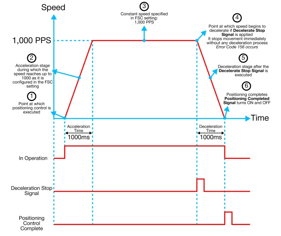
- The FSC command performs speed control in the positive direction.
- The speed control output the speed of each pulse until the deceleration stop request is entered (Control Flag, Offset 0 or 10, Bit 1).
- The current position address is cleared to 0 or fixed during speed control.
- Determined by position address under speed control in the parameter.
Position Data Example
| Position Data No. | Control Pattern | Interpolation | Acceleration Time | Deceleration Time | Control Code | Dwell Time | Operation Speed | Target Address |
|---|
| 1 | Single Step | Non-Interpolation | No. 1 | No. 1 | FSC | 0 | 1,000 | 0 |
RSC (Reverse Speed Control)
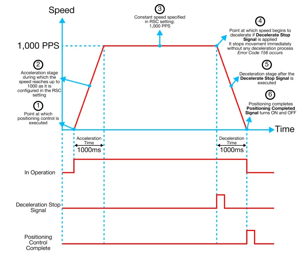
- The RSC command performs speed control in the negative direction.
- The speed control output the speed of each pulse until the deceleration stop request is entered (Control Flag, Offset 0 or 10, Bit 1).
- The current position address is cleared to 0 or fixed during speed control.
- Determined by position address under speed control in the parameter.
Position Data Example
| Position Data No. | Control Pattern | Interpolation | Acceleration Time | Deceleration Time | Control Code | Dwell Time | Operation Speed | Target Address |
|---|
| 1 | Single Step | Non-Interpolation | No. 1 | No. 1 | RSC | 0 | 1,000 | 0 |
NOP (No Operation)
- No operation is performed
LOOP & LEND
- The LOOP command is used for repeated control.
- The LEND command specifies the end of the LOOP command.
- The commands contained between LOOP and LEND are repeated by the number assigned to the target address of the LOOP command.
- The control pattern for each command between LOOP and LEND must be set to Continuous.
- The LOOP and LEND commands must both be Continuous as well.
- Nesting loops is supported.
EXAMPLE: The ABS, INC, and ABS commands will execute positioning 3 times as specified by the target address in the LOOP command.
Position Data Example
| Position Data No. | Control Pattern | Interpolation | Acceleration Time | Deceleration Time | Control Code | Dwell Time | Operation Speed | Target Address |
|---|
| 1 | Continuous | Non-Interpolation | No. 1 | No. 1 | Loop | 0 | 1 | 3 |
| 2 | Continuous | Non-Interpolation | No. 1 | No. 1 | ABS | 0 | 1,000 | -1,000 |
| 3 | Continuous | Non-Interpolation | No. 1 | No. 1 | INC | 0 | 1,500 | 2,000 |
| 4 | Continuous | Non-Interpolation | No. 1 | No. 1 | ABS | 0 | 2,000 | -2,000 |
| 5 | Continuous | Non-Interpolation | No. 1 | No. 1 | LEND | 0 | 1 | 0 |
POS (Change Current Position)
- The POS command will force change the current position to the position assigned by the target address.
- EXAMPLE: The current position will be set to the target address: 4,000.
Position Data Example
| Position Data No. | Control Pattern | Interpolation | Acceleration Time | Deceleration Time | Control Code | Dwell Time | Operation Speed | Target Address |
|---|
| 1 | Single Step | Non-Interpolation | No. 1 | No. 1 | POS | 0 | 1,000 | 4,000 |
JUMP
- The JUMP command is used to control the positioning operation so that it jumps to a positioning data number.
- This is set in the positioning data during Continuous control.
- The JUMP command enables repeating of the same positioning control.
