Instruction Parameters
Supported PLC Series
| PLC-AES | PLC-FB | PLC-ES |
|---|---|---|
| ✓ | ✓ | ✓ |
Supported Data Registers
| M | X | Y | K | L | F | T | C | S | Z | R | Q | D | @D | Constant | |
|---|---|---|---|---|---|---|---|---|---|---|---|---|---|---|---|
| S1 | ✓ | ✓ | ✓ | ✓ | ✓ | ✓ | ✓ | ✓ | – | ✓ | ✓ | ✓ | ✓ | ✓ | ✓ |
| S2 | ✓ | ✓ | ✓ | ✓ | ✓ | ✓ | ✓ | ✓ | – | ✓ | ✓ | ✓ | ✓ | ✓ | ✓ |
| D | ✓ | – | ✓ | ✓ | ✓ | – | ✓ | ✓ | – | ✓ | ✓ | ✓ | ✓ | ✓ | – |
Supported Flags
| Flag | Bit | Support |
|---|---|---|
| Error | F11.0 | ✓ |
| Zero | F11.1 | – |
| Carry | F11.2 | – |
Number of Steps
| Steps |
|---|
| 4 |
Operands
| Operand | Description |
|---|---|
| S1 | The first operand. Entries are DWORD data registers or constants. The signed value range is -2,147,483,648 ~ 2,147,483,647 (232). The unsigned value range is 0 ~ 4,294,967,295 (232-1). The Hexadecimal value range is H00000000 ~ HFFFFFFFF. |
| S2 | The second operand. Entries are DWORD data registers or constants. The signed value range is -2,147,483,648 ~ 2,147,483,647 (232). The unsigned value range is 0 ~ 4,294,967,295 (232-1). The Hexadecimal value range is H00000000 ~ HFFFFFFFF. |
| D | The third operand. Entries are only DWORD data registers. This is where the sum is saved. |
Notice
Error Flag (F11.0) Notice
The error flag, F11.0, will be ON for one scan when the address of the data register assigned by @D exceeds the range of the data register, D. The range of the data register, D, is dependent on the CPU type. F11.0 turns ON when the value of the data for adding exceeds the data register assigned to S1 or S2.
Signed Overflow
DWORD data register entry behaves as follows:
- If the value of S1 or S2 exceeds the smallest signed value -2,147,483,648, the value will be set to -2,147,483,648 with no warning.
- If the value of S1 or S2 exceeds the largest signed value 2,147,483,647, the value will be set to 2,147,483,647 with no warning.
Tip: Signed Notation
The signed value range for DADD and DADDP is -2,147,483,648 ~ 2,147,483,647 (232). – If the DADD or DADDP instruction is executed while the value for the sum data register, D, is 2,147,483,647, the overflow value for the sum data register, D, will begin at -2,147,483,648. – If the DADD or DADDP instruction is executed while the value for the sum data register, D, is -2,147,483,648, the overflow value for the sum data register, D, will begin at 2,147,483,647 if the number being added is -1.
Ladder Diagram Examples
DADD

The DADD instruction adds a DWORD value, S1, to a DWORD value, S2, and saves the sum in an assigned DWORD data register, D.

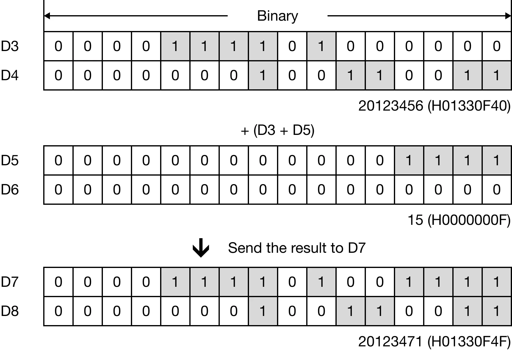
When M0.0 is powered ON, the data register DWORD data register, D3, is added to the data register DWORD data register, D5, and the sum saved in the DWORD data register, D7.

Memory Monitor
DADDP

The DADDP one-shot instruction adds a DWORD value, S1, to a DWORD value, S2, and saves the sum in an assigned DWORD data register, D. Every time this instruction executes, it energizes the output only once.

When M0.0 is powered ON, the data register DWORD data register, D3, is added to the data register DWORD data register, D5, and the sum saved in the DWORD data register, D7.

Memory Monitor