
PWM Module Buffer Memory
To write to buffer memory, use the TO instruction.
To read from buffer memory, use the FROM instruction.
Please refer to the table below for writing to and reading from buffer memory.
The IO-SD0032PPWM expansion module reserves 64 WORDs of buffer memory.
| Memory Address (Hexadecimal) | Memory Address (Decimal) | Details | Read | Write |
|---|---|---|---|---|
| 00H | 0 | PWM Output Enable | ✓ | ✓ |
| 01H | 1 | Frequency 1, 2, 3, and 4 | ✓ | ✓ |
| 02H | 2 | Frequency 5, 6, 7, and 8 | ✓ | ✓ |
| 03H | 3 | Frequency 9, 10, 11, and 12 | ✓ | ✓ |
| 04H | 4 | Reserved | – | – |
| 05H | 5 | Frequency RAMP Control Time Channels 1, 2, 3, and 4 | ✓ | ✓ |
| 06H | 6 | Frequency RAMP Control Time Channels 5, 6, 7, and 8 | ✓ | ✓ |
| 07H | 7 | Frequency RAMP Control Time Channels 9, 10, 11, and 12 | ✓ | ✓ |
| 08H | 8 | Reserved | – | – |
| 09H | 9 | Error Code | ✓ | ✓ |
| 0AH | 10 | Channel 1 DUTY Cycle Ration | ✓ | ✓ |
| 0BH | 11 | Channel 2 DUTY Cycle Ration | ✓ | ✓ |
| 0CH | 12 | Channel 3 DUTY Cycle Ration | ✓ | ✓ |
| 0DH | 13 | Channel 4 DUTY Cycle Ration | ✓ | ✓ |
| 0EH | 14 | Channel 5 DUTY Cycle Ration | ✓ | ✓ |
| 0FH | 15 | Channel 6 DUTY Cycle Ration | ✓ | ✓ |
| 10H | 16 | Channel 7 DUTY Cycle Ration | ✓ | ✓ |
| 11H | 17 | Channel 8 DUTY Cycle Ration | ✓ | ✓ |
| 12H | 18 | Channel 9 DUTY Cycle Ration | ✓ | ✓ |
| 13H | 19 | Channel 10 DUTY Cycle Ration | ✓ | ✓ |
| 14H | 20 | Channel 11 DUTY Cycle Ration | ✓ | ✓ |
| 15H | 21 | Channel 12 DUTY Cycle Ration | ✓ | ✓ |
| 16H | 22 | Reserved | – | – |
| 17H | 23 | Reserved | – | – |
| 18H | 24 | Reserved | – | – |
| 19H | 25 | Reserved | – | – |
| 1AH | 26 | Reserved | – | – |
| 1BH | 27 | Reserved | – | – |
| 1CH | 28 | Reserved | – | – |
| 1DH | 29 | Reserved | – | – |
| 1EH | 30 | Channel 1 DUTY Cycle RAMP Time (× 10ms) | ✓ | ✓ |
| 1FH | 31 | Channel 2 DUTY Cycle RAMP Time (× 10ms) | ✓ | ✓ |
| 20H | 32 | Channel 3 DUTY Cycle RAMP Time (× 10ms) | ✓ | ✓ |
| 21H | 33 | Channel 4 DUTY Cycle RAMP Time (× 10ms) | ✓ | ✓ |
| 22H | 34 | Channel 5 DUTY Cycle RAMP Time (× 10ms) | ✓ | ✓ |
| 23H | 35 | Channel 6 DUTY Cycle RAMP Time (× 10ms) | ✓ | ✓ |
| 24H | 36 | Channel 7 DUTY Cycle RAMP Time (× 10ms) | ✓ | ✓ |
| 25H | 37 | Channel 8 DUTY Cycle RAMP Time (× 10ms) | ✓ | ✓ |
| 26H | 38 | Channel 9 DUTY Cycle RAMP Time (× 10ms) | ✓ | ✓ |
| 27H | 39 | Channel 10 DUTY Cycle RAMP Time (× 10ms) | ✓ | ✓ |
| 28H | 40 | Channel 11 DUTY Cycle RAMP Time (× 10ms) | ✓ | ✓ |
| 29H | 41 | Channel 12 DUTY Cycle RAMP Time (× 10ms) | ✓ | ✓ |
| 2AH | 42 | Reserved | – | – |
| 2BH | 43 | Reserved | – | – |
| 2CH | 44 | Reserved | – | – |
| 2DH | 45 | Reserved | – | – |
| 2EH | 46 | Reserved | – | – |
| 2FH | 47 | Reserved | – | – |
| 30H | 48 | Reserved | – | – |
| 31H | 49 | Reserved | – | – |
| 32H | 50 | Reserved | – | – |
| 33H | 51 | Reserved | – | – |
| 34H | 52 | Reserved | – | – |
| 35H | 53 | Reserved | – | – |
| 36H | 54 | Reserved | – | – |
| 37H | 55 | Reserved | – | – |
| 38H | 56 | Reserved | – | – |
| 39H | 57 | Reserved | – | – |
| 3AH | 58 | Reserved | – | – |
| 3BH | 59 | Reserved | – | – |
| 3CH | 60 | Reserved | – | – |
| 3DH | 61 | Reserved | – | – |
| 3EH | 62 | Reserved | – | – |
| 3FH | 63 | OS Version | – | – |
Pulse-Width Modulation Output Enable
- The pulse-width modulation output enable will enable the channels for pulse-width modulation when set to 1 or general digital output when set to 0.
- The PWM output function can be enabled by using the TO instruction.
| Buffer Memory | Bit 0 | Bit 1 | Bit 2 | Bit 3 | Bit 4 | Bit 5 | Bit 6 | Bit 7 | Bit 8 | Bit 9 | Bit 10 | Bit 11 | Bit 12 | Bit 13 | Bit 14 | Bit 15 |
|---|---|---|---|---|---|---|---|---|---|---|---|---|---|---|---|---|
| Channel Number | CH 1 | CH 2 | CH 3 | CH 4 | CH 5 | CH 6 | CH 7 | CH 8 | CH 9 | CH 10 | CH 11 | CH 12 | X | X | X | X |
Frequency Control
- The pulse-width modulation supports functions to control the frequency range from 0~4,000pps.
- 4 channels per group can be controlled.
- A total of 3 groups can be controlled.
- 4 channels per group can be controlled.
- The frequencies of each group are set by the TO instruction.
| Frequency A or General Digital Output | Frequency B or General Digital Output | Frequency C or General Digital Output |
|---|---|---|
| Channel 1 (Yn.2) | Channel 5 (Yn.A) | Channel 9 (Yn + 1.2) |
| Channel 2 (Yn.3) | Channel 6 (Yn.B) | Channel 10 (Yn + 1.3) |
| Channel 3 (Yn.6) | Channel 7 (Yn.C) | Channel 11 (Yn + 1.4) |
| Channel 4 (Yn.7) | Channel 8 (Yn.D) | Channel 12 (Yn + 1.5) |
- Every 4 PWM output included in a group are operated in the same frequency.
- 3 different frequency outputs are available at the same time since 3 groups are offered.
- When the TO instruction is operated on the buffer memory, the output terminal outputs the designated frequency instantly.
- To prevent a sharp change of frequency, refer to frequency RAMP control.
- If the frequency value is over 4,000pps, both the valid range of the DUTY cycle and degree of precision are decreased
| Frequency (pps) | Minimum Value of DUTY Cycle (%) | Maximum Value of DUTY Cycle (%) |
|---|---|---|
| 5,000 | 1.0 | 98.0 |
| 10,000 | 1.5 | 95.0 |
| 15,000 | 3.0 | 94.0 |
| 20,000 | 4.0 | 93.0 |
| 25,000 | 5.0 | 91.0 |
| 30,000 | 6.0 | 89.0 |
| 35,000 | 7.0 | 87.0 |
| 40,000 | 9.0 | 85.0 |
| 45,000 | 10.0 | 83.0 |
| 50,000 | 12.0 | 82.0 |
| 55,000 | 13.0 | 80.0 |
| 60,000 | 14.0 | 78.0 |
| 65,000 | 15.0 | 75.0 |
RAMP Control
- RAMP control can be used to prevent a sharp change of the frequency and DUTY cycle.
- The output will be gradually changed during the RAMP control time, which the value of the frequency or DUTY cycle have configured.
- When the set value of the RAMP control time of buffer memory is 0, output will be changed immediately.
- The following is a method for RAMP control:
- Change the RAMP control time before the value to control as intended.
- In case of a power reset or CPU STOP during the RAMP operation, reset the value again by using the TO instruction.
- he value of the buffer memory will be set back to the initial value, 0.
Frequency RAMP Control Time
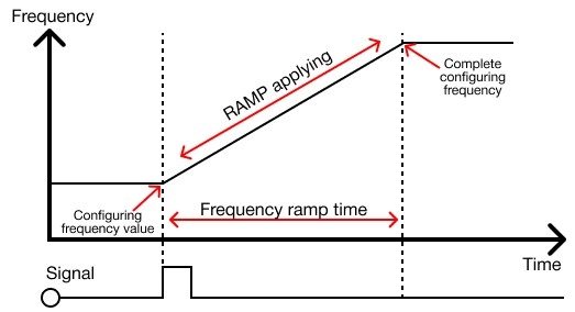
- The frequency will be changed through the set RAMP control time when the frequency value is changed after setting the frequency RAMP control time.
- The frequency RAMP control time can be set by using the TO instruction.
- In case the frequency RAMP control time is changed during the RAMP operation, it will be applied to the NEXT RAMP operation.
- In case of a power reset or CPU STOP during the RAMP operation, reset the value again by using the TO instruction.
Controlling DUTY Cycle
- The pulse-width modulation supports functions to control the DUTY cycle 0.0% ~ 100.0% within 1/1,000 resolution.
- The DUTY cycles are able to be controlled per channel for a total of 12 channels.
- The DUTY cycle can be set using the TO instruction.
- When the TO instruction is operated, the output terminal will be configured to set the DUTY cycle and being output.
- To prevent a sharp change of frequency, refer to frequency RAMP control.
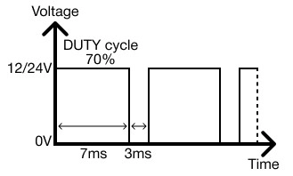
- If the digital signal of +12V-+24V voltage is set to the DUTY cycle 70.0% (as shown above), the voltage output of +8.4V-+16.8V in average is available.
- The DUTY cycle control (PWM) can be utilized in various ways of substituting an analog signal.
- Controlling the speed of a motor, switch, or ratio of a value are examples.
DUTY Cycle RAMP Control
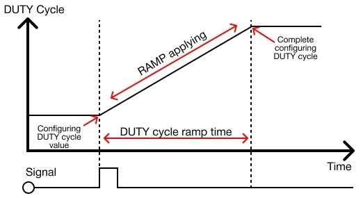
- If the DUTY cycle’s value is configured after setting the DUTY cycle RAMP control time, the DUTY cycle will be gradually changed during the set RAMP control time.
- The DUTY cycle ratio can be set using the TO instruction.
- In case the DUTY cycle ramp control time is configured during the AMP operation, it will be applied to the NEXT RAMP operation.
- In case of a power reset or CPU STOP during the RAMP operation, reset the value again by using the TO instruction.
- The value of the buffer memory will be set back to the initial value, 0.