
Type of Pulse Input Method
1-Phase 1-Multiplication
Counting Up
- The HSC module counts at the rising edges of øA.
- øB is OFF.
Counting Down
- The HSC module counts at the falling edges of øA.
- øB is ON.
1-Phase 2-Multiplication
Counting Up
- The HSC module counts at the rising and falling edges of øA.
- øB is OFF.
Counting Down
- The HSC module counts at the rising and falling edges of øA.
- øB is ON.
Clockwise Counter-Clockwise
Counting Up
- The HSC module counts at the rising edges of øA.
- øB is OFF.
Counting Down
- øA is OFF.
- The HSC module counts at the falling edges of øB.
2-Phase 1-Multiplication
Counting Up
- When øB is OFF, the HSC module counts at the rising edges of øA.
Counting Down
- When øB is OFF, the HSC module counts at the falling edges of øA.
2-Phase 2-Multiplication
Counting Up
- When øB is OFF, the HSC module counts at the rising edges of øA.
- When øB is ON, the HSC module counts at the falling edges of øA.
Counting Down
- When øB is ON, the HSC module counts at the rising edges of øA.
- When øB is OFF, the HSC module counts at the falling edges of øA.
2-Phase 4-Multiplication
Counting Up
- When øB is OFF, the HSC module counts at the rising edges of øA.
- When øB is ON, the HSC module counts at the falling edges of øA.
- When øA is OFF, the HSC module counts at the falling edges of øB.
- When øA is ON, the HSC module counts at the rising edges of øB.
Counting Down
- When øB is ON, the HSC module counts at the rising edges of øA.
- When øB is OFF, the HSC module counts at the falling edges of øA.
- When øA is ON, the HSC module counts at the falling edges of øB.
- When øA is OFF, the HSC module counts at the rising edges of øB.
1-Phase Pulse Input
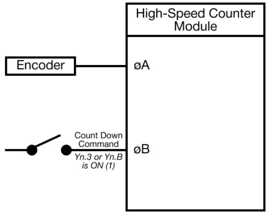
1-Phase 1-Multiplication or 1-Phase 2-Multiplication can be selected.
Clockwise/Counter-Clockwise Pulse Input
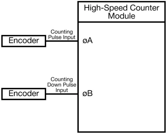
If there is a pulse in the A Phase, the module counts up. If there is a pulse in the B Phase, the module counts down.
2-Phase Pulse Input
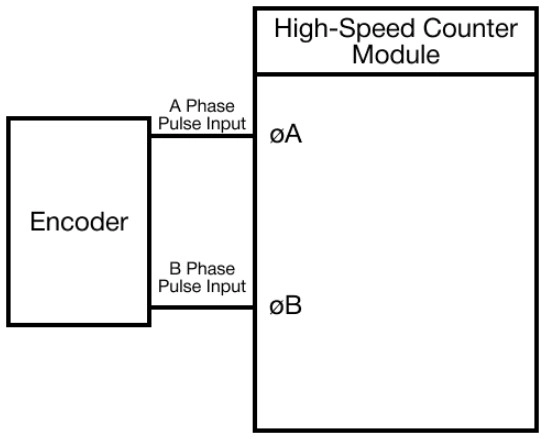
2-Phase 1-Multiplication, 2-Phase 2-Multiplication, or 2-Phase 4-Multiplication can be selected.
Counting Forms
- When the values are linear and ring-counted:
- In the case that the currently-counted value is greater than the maximum ring-counted value, it is preset as the value less than or equal to the maximum ring-counted value to ring-count when being linear-counted.
- It is to be preset as the value greater than or equal to the minimum ring-counted value to ring count when being linear-counted down.
- If the value is not preset, it will be linear-counted.
- Maximum ring-counted value > Minimum ring-counted value
Linear Counting
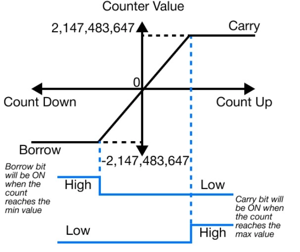
- If linear counting is selected, input pulses are counted in the range from -2,147,483,648 ~ 2,147,483,647 (232).
- This is used in the combination of the presetting and coincidence output functions.
Overflow Error
- This occurs when the value is linear-counted down past -2,147,483,648 or up past 2,147,483,647.
- If overflow occurs, the data registers for detecting overflow in buffer memory 02H (2) or 22H (33) will be set, and the counting will stop.
- Even though pulse inputs pulse continuously, the counted value is fixed at -2,147,483,648 or -2,147,483,647.
- If the value is preset, the overflow error will be cleared, and the data register for detecting overflow in buffer memory will be 0.
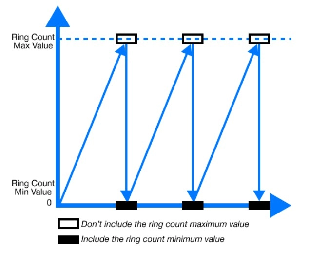
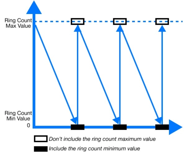
Ring Counting
- If ring counting is selected, input pulses are counted repeatedly between the minimum ring-counted value, 16H (22), 17H (23), or 36H (54), 37H (55), and the maximum ring-counted value, 18H (24), 19H (25) or 38H (56), 39H (57).
- The overflow for ring counting does not occur.
- Ring counting is used in combination with the presetting and coincidence output functions.
Counting Up
Counting Down
Range of Ring Counting
- The range of ring-counted pulses is from the minimum value, 16H (22), 17H (23), or 36H (54), 37H (55), to the maximum value, 18H (24), 19H (25) or 38H (56), 39H (57).
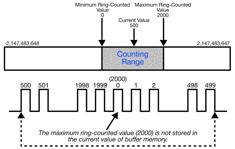
Option 1: Minimum Ring-Counted Value ≤ Current Value ≤ Maximum Ring-Counted Value
- Counting Up:
- In the case that the currently-counted value reaches the maximum ring-counted value, the minimum ring-counted value is automatically stored in the current value.
- Counting Down:
- In the case that the currently-counted value reaches the minimum ring-counted value, when the next counting-down pulse pulses, the value, maximum ring-counted value – 1, is stored in the current value.
- While input pulses are being counted up or down, the maximum ring-counted value is not stored in the currently-counted value of buffer memory.
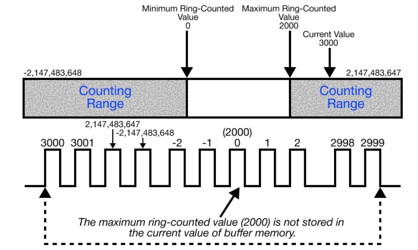
Option 2: Current Value ≤ Minimum Ring-Counted Value, Current Value ≥ Maximum Ring-Counted Value
- Counting Up:
- In the case that the currently-counted value reaches the minimum ring-counted value, when the next counting pulse pulses, the value, maximum ring-counted value + 1, is stored in the current value.
- Counting Down:
- In the case that the currently-counted value reaches the maximum ring-counted value, the minimum ring-counted value is automatically stored in the current value.
- While input pulses are being counted up or down, the maximum ring-counted value is not stored in the currently-counted value of buffer memory.
Option 3: Maximum Ring-Counted Value = Minimum Ring-Counted Value
- Any value in the range -2,147,483,648 ~ 2,147,483,647 (232) can be ring-counted regardless of the current value.
Coincidence Output
- The coincidence output is used to output a coincidence signal when the currently-counted value is compared, being coincided with a set value.
- The coincidence output can be set for 2 points on each channel.
- To output a coincidence signal, enable the coincidence output.
- Channel 1: Yn.2
- Channel 2: Yn.A
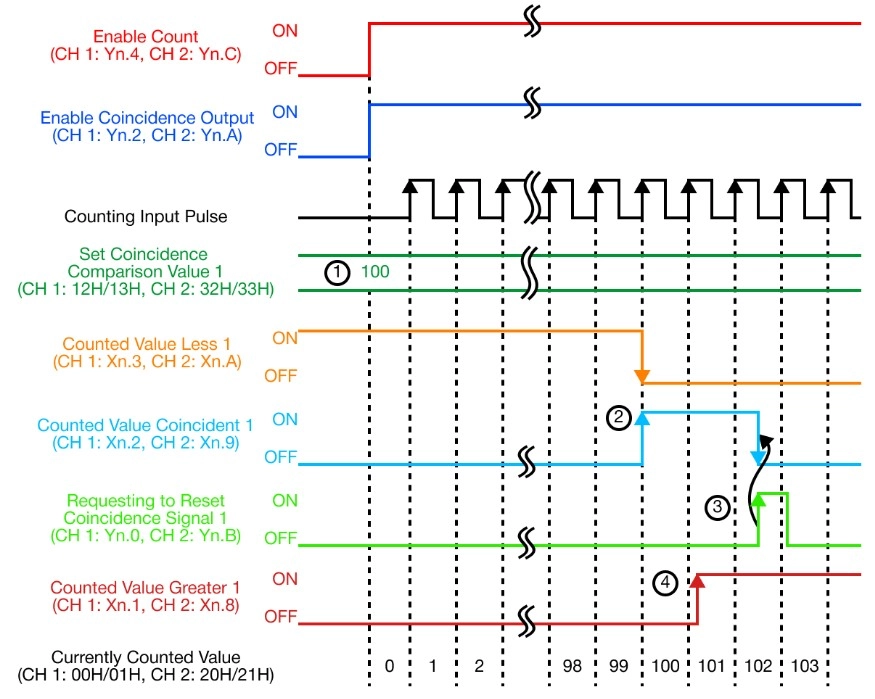
| Number | Description |
|---|---|
| 1 | The set coincidence output value is stored in the set coincidence comparison value 1 in the range -2,147,483,648 ~ 2,147,483,647 (232). Channel 1: 12H (18), 13H (19) Channel 2: 32H (50), 33H (51) |
| 2 | When the currently-counted value is equal to the set coincidence output value, the counted value less is OFF and the counted value coincident is ON. |
| 3 | If the requesting to reset coincidence signal 1 or requesting to reset coincidence signal 2 is ON, the counted value coincident is reset. If the counted value coincident is kept ON, the next coincidence signal is not output. |
| 4 | If the counted value is greater than the set coincidence output value, the counted value greater is ON. |
Presetting
- Presetting is used to write the currently-counted value in as an integer value as a preset value.
- There are two presetting methods:
- Sequence program
- Outer control signal
- There are two presetting methods:
Presetting by Sequence Program
- If Yn.1* or *Yn.9 is turned ON by the sequence program, the currently-counted value is preset.
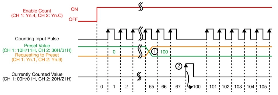
| Number | Description |
|---|---|
| 1 | The number is stored in the preset value of the buffer memory in the range -2,147,483,648 ~ 2,147,483,647 (232). Channel 1: 10H (16), 11H (17) Channel 2: 31H (49), 32H (50) |
| 2 | At the rising edge of the requesting to preset (Yn.1 or Yn.9), from OFF to ON, the currently-counted value of the buffer memory is set up as the preset value of the buffer memory. The value is preset irrelevantly to the enable counting (Yn.4 or Yn.C). |
Presetting by Outer Control Signal
- If a voltage is input into a presetting input terminal, the currently-counted value is preset.
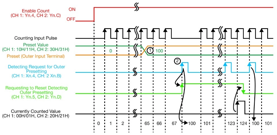
| Number | Description |
|---|---|
| 1 | The number is stored in the preset value of the buffer memory in the range -2,147,483,648 ~ 2,147,483,647 (232). Channel 1: 10H (16), 11H (17) Channel 2: 31H (49), 32H (50) |
| 2 | At the rising edge of the voltage input into an outer input terminal, from OFF to ON, the currently-counted value of buffer memory is set up as the preset value of buffer memory. The value is preset irrelevantly to the enable counting (Yn.4 or Yn.C). |
IMPORTANT NOTE:
- If the detect request for outer presetting flag (Xn.4 or Xn.B) is ON, even though the voltage input into an outer preset terminal or requesting to preset (Yn.1 or Yn.9) is set, the currently-counted value is not preset.
- In this case, to preset, reset detecting outer presetting (Yn.5 or Yn.D) is to be set and the detecting request for outer presetting flag is to be OFF.
- Even though the outer presetting input is set while the requesting to reset detecting outer presetting (Yn.5 or Yn.D) is ON, a value is not preset.