Instruction Parameters
Supported PLC Series
| PLC-AES | PLC-FB | PLC-ES |
|---|---|---|
| ✓ | ✓ | ✓ |
Supported Data Registers
| M | X | Y | K | L | F | T | C | S | Z | R | Q | D | @D | Constant | |
|---|---|---|---|---|---|---|---|---|---|---|---|---|---|---|---|
| S | ✓ | ✓ | ✓ | ✓ | ✓ | – | – | – | – | ✓ | ✓ | ✓ | ✓ | ✓ | – |
| D | ✓ | – | ✓ | ✓ | ✓ | – | – | – | – | ✓ | ✓ | ✓ | ✓ | ✓ | – |
| P | ✓ | – | ✓ | ✓ | ✓ | – | – | – | – | ✓ | ✓ | ✓ | ✓ | ✓ | – |
| n | ✓ | ✓ | ✓ | ✓ | ✓ | ✓ | ✓ | ✓ | – | ✓ | ✓ | ✓ | ✓ | ✓ | ✓ |
Supported Flags
| Flag | Bit | Support |
|---|---|---|
| Error | F11.0 | ✓ |
| Zero | F11.1 | – |
| Carry | F11.2 | – |
Number of Steps
| Steps |
|---|
| 5 |
Operands
| Operand | Description |
|---|---|
| S | The first operand. Entries are only DWORD data registers. This is the data to be scaled. The signed value range is -2,147,483,648 ~ 2,147,483,647 (232). The unsigned value range is 0 ~ 4,294,967,295 (232-1). The Hexadecimal value range is H00000000 ~ HFFFFFFFF. |
| D | The second operand. Entries are only DWORD data registers. This is where the result of the scaling is saved. |
| P | The third operand. Entries are only DWORD data registers. This is the data table that defines the linear function for scaling. This requires 4 DWORD data registers. |
| n | The fourth operand. Entries are WORD data registers or constants. This is the number of data registers, starting at D, to scale. |
Notice
Error Flag (F11.0) Notice
The error flag, F11.0, will be ON for one scan when the address of the data register assigned by @D exceeds the range of the data register, D. The range of the data register, D, is dependent on the CPU type. F11.0 turns ON when the value of S exceeds the scaling range defined in P or when D exceeds its defined range. The value assigned to n must not exceed the range of the corresponding data register. If the assigned value exceeds the range of the area assigned to the data registers S and D, it may cause a PLC CPU STOP command.
Scaling Table (P)
The P operand data register stores data in the following:
| Data Register | Description | Axis |
|---|---|---|
| P P+1 | Range start point of the data to be scaled. Raw minimum value. Start S | X |
| P+2 P+3 | Range end point of the data to be scaled. Raw maximum value. End S | X |
| P+4 P+5 | Range start point of scaled data. Scaled minimum value. Start D | Y |
| P+6 P+7 | Range end point of scaled data. Scaled maximum value. End D | Y |
Scaling Equations
The equations for scaling are as follows:
- Destination (D) = Source (S) × Gradient + Offset
- Gradient = (End D – Start D) ÷ (End S – Start S)
- Offset (Y-intercept) = End D – Gradient × End S
Instruction Behavior
The DSCL and DSCLP instructions behave as follows:
- When the data assigned to the data register S exceeds the range between Start S and End S, the data is converted into the value assigned to Start D or End D.
- The value is converted to Start D when the value assigned to the data register S is less than Start S.
- The value is converted to End D when the value assigned to the data register S is greater than End S.
- When Gradient is negative, the data assigned to the data register S is converted into the value assigned to End D and Start D.
- The value is converted to End D when the value assigned to the data register S is less than Start S.
- The value is converted to Start D when the value assigned to the data register S is greater than End S.
- The value assigned to n must not exceed the range of the corresponding data register.
- If the assigned value exceeds the range of the area assigned to the data registers S and D, it may cause a PLC CPU STOP command.
Ladder Diagram Examples
DSCL

The DSCL instruction scales n number of DWORD data registers starting from the data register, S, on a linear function defined by the data table, P. The scaled data is saved into n number of DWORD data registers starting at D.

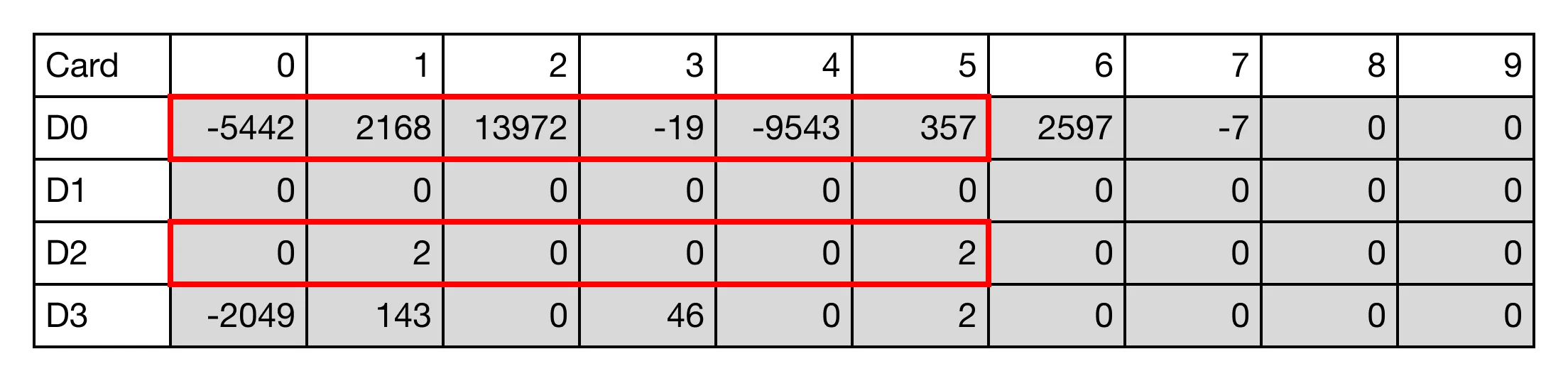
When the contact, M0.0, is powered ON (1), the instruction scales 3 REAL data registers starting at D40 by the data register, D30, and saves the result in the data register, D20.

Result
DSCLP

The DSCLP one-shot instruction scales n number of DWORD data registers starting from the data register, S, on a linear function defined by the data table, P. The scaled data is saved into n number of DWORD data registers starting at D. Every time this instruction executes, it energizes the output only once.

When the contact, M0.1, is powered ON (1), the instruction scales 3 REAL data registers starting at D40 by the data register, D60, and saves the result in the data register, D70.

Result