
Instruction Parameters
Supported PLC Series
| PLC-AES | PLC-FB | PLC-ES |
|---|---|---|
| ✓ | ✓ | ✓ |
Supported Data Registers
| M | X | Y | K | L | F | T | C | S | Z | R | Q | D | @D | Constant | |
|---|---|---|---|---|---|---|---|---|---|---|---|---|---|---|---|
| D | ✓ | – | ✓ | ✓ | ✓ | – | ✓ | ✓ | – | ✓ | – | ✓ | ✓ | ✓ | – |
Supported Flags
| Flag | Bit | Support |
|---|---|---|
| Error | F11.0 | ✓ |
| Zero | F11.1 | – |
| Carry | F11.2 | – |
Number of Steps
| Steps |
|---|
| 3 |
Operands
| Operand | Description |
|---|---|
| D | The first operand. Entries are only WORD data registers. This is where the values read from the real time clock (RTC) device are stored. This requires 7 data registers. |
Notice
Error Flag (F11.0) Notice
The error flag, F11.0, will be ON for one scan when the address of the data register assigned by @D exceeds the range of the data register, D. The range of the data register, D, is dependent on the CPU type.
RTC Data Storage
The data read from a real time clock (RTC) device are stored in the data register, D, as follows:
| Data Register | Value | Date Range |
|---|---|---|
| D | Year | 2000 ~ 2099 |
| D+1 | Month | 1 ~ 12 |
| D+2 | Day | 1 ~ 31 |
| D+3 | Hour | 0 ~ 23 |
| D+4 | Minute | 0 ~ 59 |
| D+5 | Second | 0 ~ 59 |
| D+6 | Day of the Week | 0 ~ 6 Sunday ~ Saturday |
Instruction Behavior
The DATERD and DATERDP instructions behave as follows:
- The day of the week is defined by 0 ~ 6.
- Day 0 is Sunday, day 6 is Saturday.
- Compensation is made automatically for leap years.
Ladder Diagram Examples
DATERD

The DATERD instruction reads the date from a real time clock (RTC) device and stores the date in 7 WORD data registers starting at D.


When the contact, M0.0, is powered ON (1), the instruction reads the current date and time from the real time clock (RTC) device.
Memory Monitor
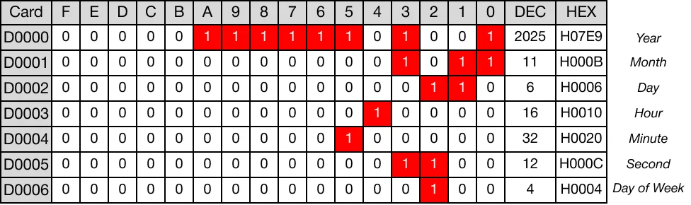
- The following data is saved into the data registers, D0, D1, D2, D3, D4, D5, and D6:
- D0: Year (2025)
- D1: Month (11, November)
- D2: Day (6)
- D3: Hour (16)
- D4: Minute (32)
- D5: Second (12)
- D6: Day of the week (4, Thursday)
The clock time reads: 4:32:12 P.M., Thursday, November 6, 2025.
DATERDP

The DATERDP one-shot instruction reads the date from a real time clock (RTC) device and stores the date in 7 WORD data registers starting at D. Every time this instruction executes, it energizes the output only once.


When the contact, M0.1, is powered ON (1), the instruction reads the current date and time from the real time clock (RTC) device.
Memory Monitor
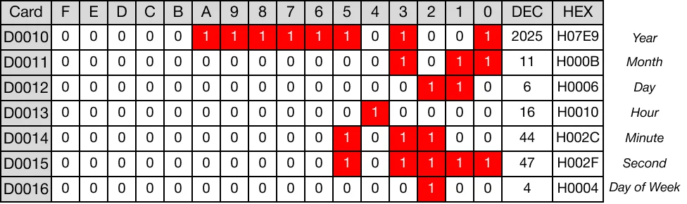
- The following data is saved into the data registers, D10, D11, D12, D13, D14, D15, and D16:
- D10: Year (2025)
- D11: Month (11, November)
- D12: Day (6)
- D13: Hour (16)
- D14: Minute (44)
- D15: Second (47)
- D16: Day of the week (4, Thursday)
The clock time reads: 4:44:47 P.M., Thursday, November 6, 2025.