
Online Ladder Diagram Notation
- When the PLC is running the program, there are indications in the ladder that display changes being made.
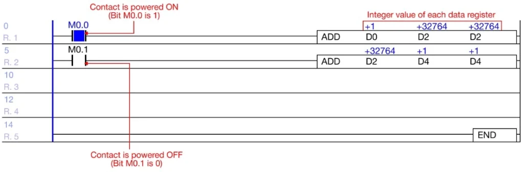
- The blue square in between a contact represents that the contact is receiving power, and the contact is ON (1).
- When a contact does NOT have a blue square, the contact is not receiving power, and the contact is OFF (0).
- Blue values will appear over the data registers if there have a value assigned.
- This representation the integer value of the data registers.
- The notation siplays are signed, unsigned, and Hexadecimal.
- This representation the integer value of the data registers.
Change Value Notation

- To change the value notation to signed, unsigned, and hexadecimal, left-click the Notation icon.
- Left-click the Notation icon to cycle through each value notation.
Signed Values
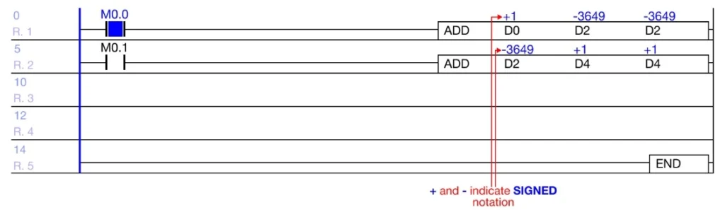
- Values with a + or – are considered signed values.
- The signed value range:
- WORD: -32,768 ~ 32,767 (216)
- DWORD: -2,147,483,648 ~ 2,147,483,647 (232)
- The signed value range:
Unsigned Values
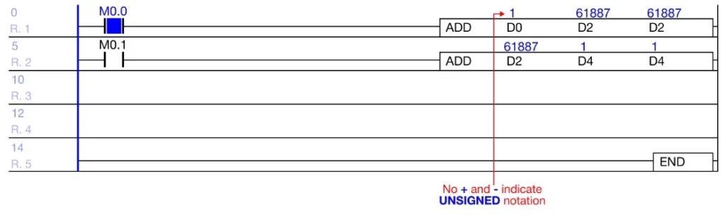
- Values without a + or – are considered unsigned values
- The unsigned value range:
- WORD: 0 ~ 65,535 (216)
- DWORD: 0 ~ 4,294,967,295 (232-1)
- The unsigned value range:
Hexadecimal Values
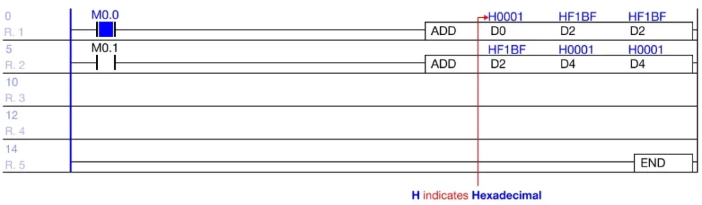
- Values with a H are considered Hexadecimal values.
- The Hexadecimal value range:
- WORD: H0000 ~ HFFFF
- DWORD: H00000000 ~ HFFFFFFFF
- The Hexadecimal value range:
Interact Online
- While the PLC is connected and running the current program it is possible to interact with the contacts and instructions to change their values.
Contact Manipulation
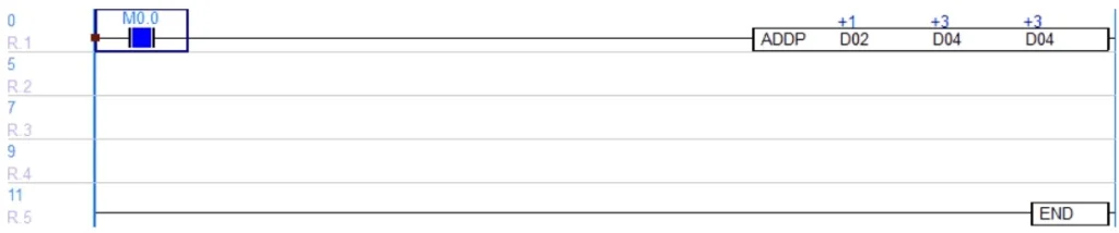
Step 1: To interact with a contact, left-click the contact and type SHIFT + ENTER.
- Data registers with write access can be interacted with.
- X data registers are read only.
- Refer below for forced I/O
- X data registers are read only.
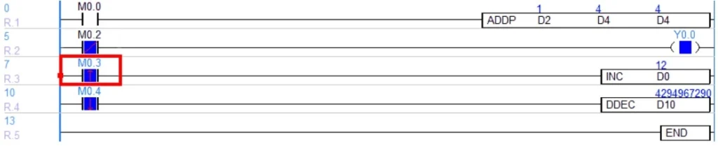
- All contact types can be interacted with.
Data Register Manipulation

Step 1: To change the data register value, left-click the instruction with a data register and type SHIFT + ENTER.
Step 2: Specify the new value for each data register and left-click OK.
- The value of the data registers has changed.
Forced I/O
- Forced I/O is used to forcibly manipulate X and Y data registers.
Step 1: Connect the PLC to the computer.
Step 2: Left-click N/D.
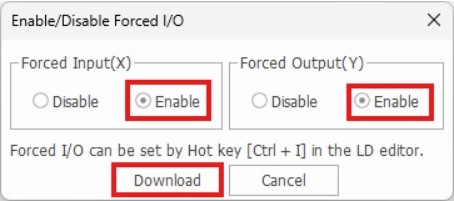
Step 3: Select the Enable option for the X and Y and left-click Download.
- The watermark will now display a blue X/Y.
- To energize/deenergize the X data register contact, type CTRL + I.
- Note: there may be a small delay after pressing.
- To energize/deenergize the Y data register contact, type CTRL + I.
- Note: there may be a small delay after pressing.