
Connection Requirements
Supported PLC Series
| PLC-AES | PLC-FB | PLC-ES |
|---|---|---|
| ✓ | ✓ | ✓ |
Supported Data Registers
| M | X | Y | K | L | F | T | C | S | Z | R | Q | D | @D | Constant | |
|---|---|---|---|---|---|---|---|---|---|---|---|---|---|---|---|
| S | ✓ | ✓ | ✓ | ✓ | ✓ | ✓ | ✓ | ✓ | ✓ | – | – | ✓ | ✓ | – | – |
Supported Flags
| Flag | Bit | Support |
|---|---|---|
| Error | F11.0 | – |
| Zero | F11.1 | – |
| Carry | F11.2 | – |
Number of Steps
| Steps |
|---|
| 1 |
Operands
| Operand | Description |
|---|---|
| S | This is the BOOL data register. This is the bit number to toggle the contact ON/OFF. When the bit is 0, the contact is OFF. When the bit is 1, the contact is ON. |
Notice
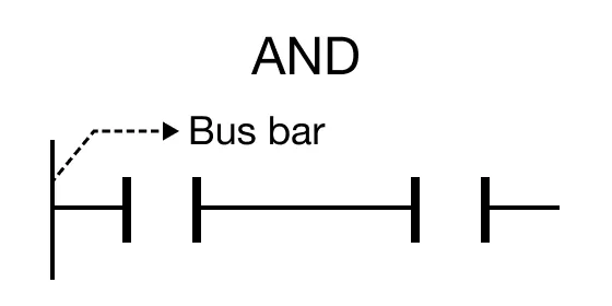
Contact Orientation
The AND contact orientation behaves as follows:
- The AND contact orientation performs a boolean AND operation based on the ON status of the assigned BOOL data register.
- The AND contact orientation performs an AND operation with the operation result to that point and uses the resulting value as a new operation result.
Ladder Diagram Examples
AND Gate Example
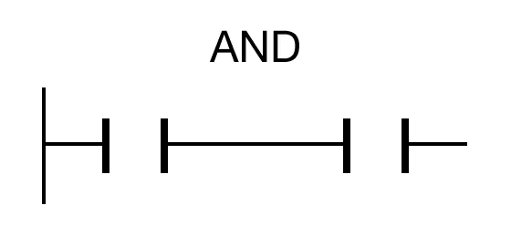
The AND contact performs a boolean AND operation based on the ON status of the assigned BOOL data register, S.

When the open contact, M17.8, is powered OFF AND the open contact, M10.4, is powered OFF, the coil, D86.4, is deenergized.

When the open contact, M17.8, is powered ON AND the open contact, M10.4, is powered OFF, the coil, D86.4, is deenergized.

When the open contact, M17.8, is powered ON AND the open contact, M10.4, is powered ON, the coil, D86.4, is energized.