
Module Memory Allocation
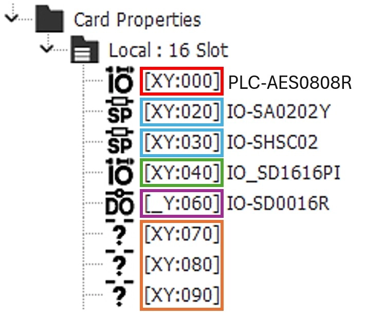
When configuring a PLC chassis, certain modules reserve a WORD (16-bits) or a DWORD (32-bits) of X (inputs) and Y (outputs).
Every WORD/DWORD is expressed in Hexadecimal form (0 ~ F (0 ~ 9, A ~ F)).
- Most modules follow these rules:
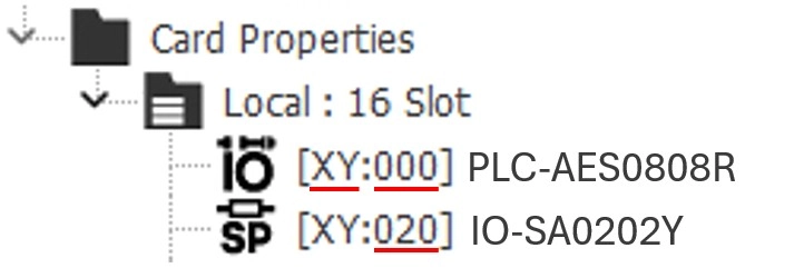
- Every CPU is allocated the first DWORD of X and the first DWORD of Y.
- X0.0 ~ X0.F (1 WORD) and X1.0 ~ X1.F (1 WORD).
- X0.0 ~ X1.F
- Y0.0 ~ Y0.F (1 WORD) and Y1.0 ~ Y1.F (1 WORD).
- Y0.0 ~ Y1.F
- IMPORTANT: for 16 input/output CPUs, the second half of X and the first half of Y are not used!
- In ladder logic, X1.0 ~ X1.F and Y0.0 ~ Y0.F are unused.
- X0.0 ~ X0.F (1 WORD) and X1.0 ~ X1.F (1 WORD).
- Every other module is allocated AT LEAST one WORD of X and one WORD of Y.
- I/O modules with 32 input/output points are allocated one DWORD of X and one DWORD of Y.
- <picture>
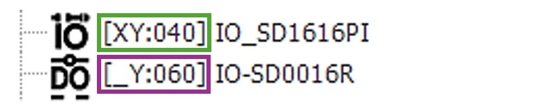
- In this example, the IO-SD1616P begins allocation at X4.0 ~ X5.F and Y4.0 ~ Y5.F (DWORD of X and Y). The following expansion module, IO-SD0016R, begins at X6.0 and Y6.0.
- If an input, button for example, is plugged into the X inputs and an output, light for example, is plugged into the Y outputs, the ladder logic will target the button between X4.0 ~ X5.F.
- In this example, the IO-SD1616P begins allocation at X4.0 ~ X5.F and Y4.0 ~ Y5.F (DWORD of X and Y). The following expansion module, IO-SD0016R, begins at X6.0 and Y6.0.
- Every module is allocated X and Y, even if it doesn’t use X or Y.

- <image>
- In this example, the IO-SD0016R is a relay output-only module. This means there are no inputs to be attached. The Card Properties window will display [_Y:####]. This represents the module only accepting outputs (Y) and no inputs (X).
- Modules that are input only will display [X_:####], meaning no outputs (Y) are accepted.
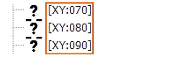
- Unallocated modules display the next WORD for allocation.
-
- If another module is added to the PLC chassis, it is allocated memory starting at X7.0 and Y7.0.
IO-SD0808R

The IO-SD0808R is a special case. The module has 8 digital inputs and 8 relay outputs.
The IO-SD0808R is allocated a WORD of X and a WORD of Y. However, to target the inputs (X) and outputs (Y) of the module, use Xn.0 ~ Xn.7 (first half of the WORD) and Yn.8-Yn.8 (second half of the WORD).
Xn.8 ~ Xn.F and Yn.0 ~ Yn.7 are unused.
n is the module’s reservation slot. Refer below.
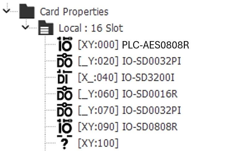
Example: In the example image, the IO-SD0808R expansion module begins reservation at WORD 7. To target the inputs (X) and outputs (Y), use X9.0 ~ X9.7 and Y9.8 ~ Y9.F.