
Instruction Parameters
Supported PLC Series
| PLC-AES | PLC-FB | PLC-ES |
|---|---|---|
| ✓ | ✓ | ✓ |
Supported Data Registers
| M | X | Y | K | L | F | T | C | S | Z | R | Q | D | @D | Constant | |
|---|---|---|---|---|---|---|---|---|---|---|---|---|---|---|---|
| n | – | – | – | – | – | – | – | – | – | – | – | – | – | – | ✓ |
Supported Flags
| Flag | Bit | Support |
|---|---|---|
| Error | F11.0 | ✓ |
| Zero | F11.1 | – |
| Carry | F11.2 | – |
Number of Steps
| Steps |
|---|
| 2 |
Operands
| Operand | Description |
|---|---|
| n | The only operand. Entries are only constants. This is the subroutine ID. The value range is 0 ~ 127. |
Notice
Subroutine Usage
The error flag, F11.0, will be ON for one scan when the address of the data register assigned by @D exceeds the range of the data register, D. The range of the data register, D, is dependent on the CPU type. The error flag, F11.0, turns ON when the instruction is processed with a CPU type such as the BP, XPnA/1R, CP3A/B/P/U, and CP4A~D/U. Errors will occur when the following conditions are met:
- Subroutine ID, n, exceeds the range 0 ~ 127.
- The CALL n or CALLP n instruction exists, but a corresponding SBRT n instruction does NOT exist.
- The SBRT and RET instructions are not used as a matching set.
- More than one SBRT n instruction with the same subroutine ID number, n, are used in the same program.
Instruction Behavior
The SBRT instruction behaves as follows:
- The subroutine program between the SBRT and RET instructions must be placed after the END instruction of the calling scan program.
- Up to 128 subroutines can be defined in one program (0 ~ 127).
- The SBRT instruction block can be nested 16 times.
Block vs. Program
This section covers information about the SBRT instruction, where a subroutine block is used. For more information about using a subroutine program, refer to the subroutine program section and the ECALL or ECALLP instructions.
Ladder Diagram Examples
SBRT

The SBRT instruction declares the start of a subroutine block.
- An existing subroutine program must be placed after the END instruction in the scan program.
- A subroutine is called using the CALL or CALLP instruction.
- The subroutine ID, n, must match the corresponding CALL or CALLP instruction.
Example 1
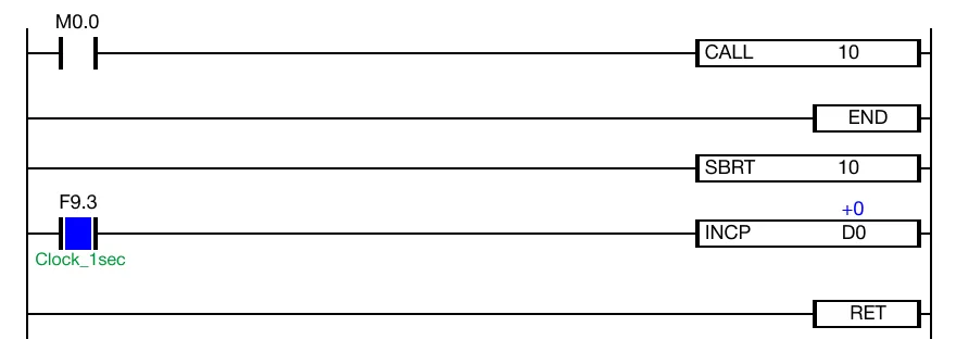
Instruction Placement
The SBRT instruction is placed after the END instruction.
When the contact, M0.0, is powered OFF (0), the CALL instruction is NOT calling the SBRT instruction. As a result, the data register, D0, is NOT increasing every 1 scan by the INCP instruction.
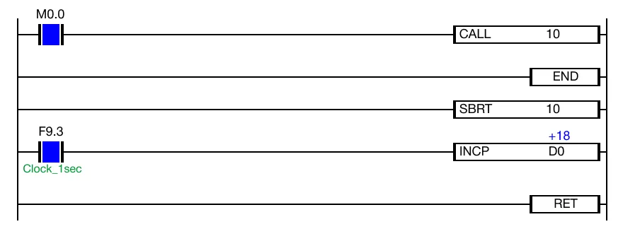
When the contact, M0.0, is powered ON (1), the CALL instruction is calling the SBRT instruction. As a result, the data register, D0, is increasing every 1 scan by the INCP instruction.
Example 2
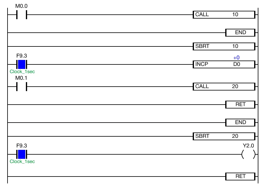
When the contact, M0.0, is powered OFF (0), the CALL instruction is NOT calling the SBRT instruction. As a result, the data register, D0, is NOT increasing every 1 scan by the INCP instruction. Additionally, the coil, Y2.0, is deenergized since the subroutine program with the ID 20 is not being called.
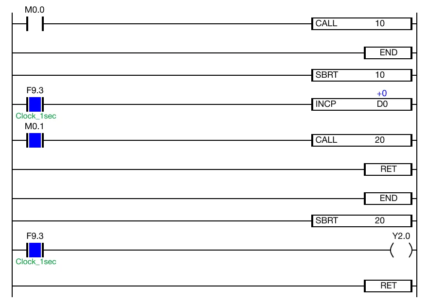
When the contact, M0.0 is powered OFF (0) and the contact, M0.1, is powered ON (1), the coil, Y2.0, remains deenergized. This is because the subroutine program with the ID 20 is not being called.
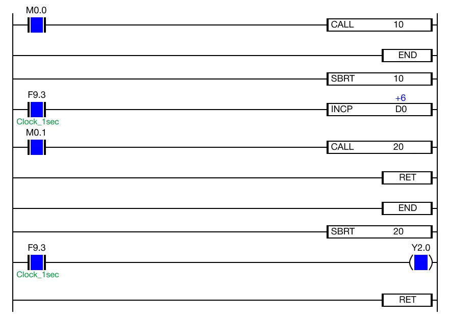
When the contacts, M0.0 and M0.1, are powered ON (1), the data register, D0, is increasing every 1 scan by the INCP instruction and the data register, Y2.0, is energizing every 1 second. Both subroutines are being called allowing both poritons of the ladder logic to execute.