
Connection Requirements
Supported PLC Series
| PLC-AES | PLC-FB | PLC-ES |
|---|---|---|
| ✓ | ✓ | ✓ |
Supported Data Registers
| M | X | Y | K | L | F | T | C | S | Z | R | Q | D | @D | Constant |
|---|---|---|---|---|---|---|---|---|---|---|---|---|---|---|
| – | – | – | – | – | – | – | – | – | – | – | – | – | – | – |
Supported Flags
| Flag | Bit | Support |
|---|---|---|
| Error | F11.0 | – |
| Zero | F11.1 | – |
| Carry | F11.2 | – |
Number of Steps
| Steps |
|---|
| 1 |
Notice
Connection Behavior
The ANB block series connection behaves as follows:
- An AND operation is performed on block A and block B and uses the new result as a new execution condition.
- ANB is not a contact signal.
- ANB is a connection signal.
- In the Instruction List (IL) mode, ANB can be written consecutively up to 15 connections (16 blocks).
- If more ANB connections are written consecutively, the operation may not be performed properly.
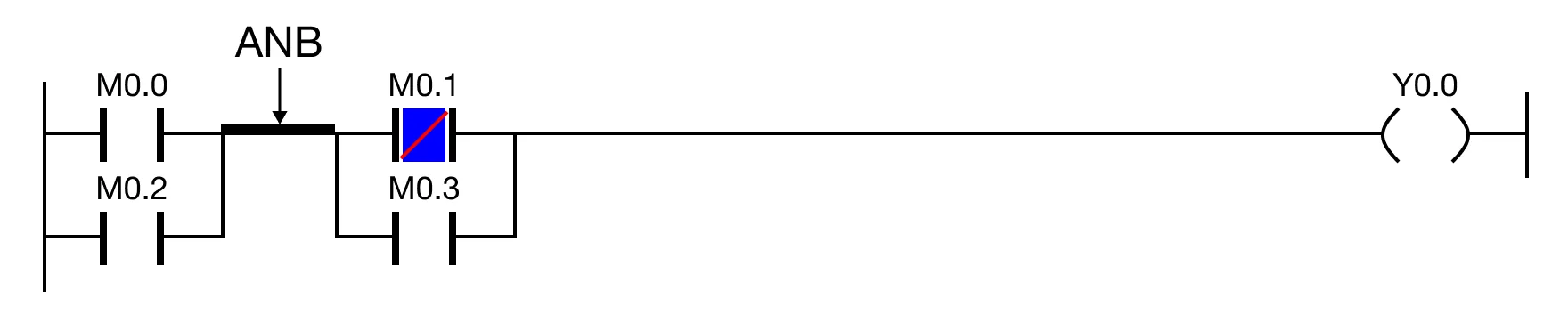
ANB refers to the bus bar connection between the two blocks horizontally.
Ladder Diagram Examples
The ANB block series connection performs an AND operation across two blocks.


The ANB block series connection can perform an AND operation diagonally across two blocks.


The ANB block series connection will NOT perform an AND operation on two contacts in the same block.

If all contacts in both blocks are powered ON, the ANB block series connection will perform an AND operation on all contacts.
