
- The PIDINIT instruction checks the items and initializes the data registers set up for a PID operation.
- The PID Control Special Program:
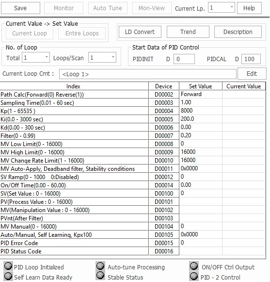
If the value of each item is 0, that item is not used in the PID calculation.
PID Control Initialization
| Offset | Item | Description | Range | Note |
|---|---|---|---|---|
| 0 | Number of Loops | – | 1 ~ 32 1 ~ 64 | Common for All Loops |
| +1 | Number of Loops for a Scan | – | 1 ~ 32 1 ~ 64 | Common for All Loops |
| +2 (0) | Operation Type | Forward Action: 0 Reverse Action: 1 | 0 or 1 | For Loops |
| +3 (+1) | Sampling Interval (Ts) | 0.01s ~ 60.00s | 1 ~ 6,000 | For Loops |
| +4 (+2) | Proportional Gain (Kp) | 0.01 ~ 300.00 | 1 ~ 30,000 | For Loops |
| +5 (+3) | Integral Gain (Ki) | 0.00s ~ 300.000s | 0 ~ 30,000 | For Loops |
| +6 (+4) | Derivative Gain (Kd) | 0.00s ~ 300.000s | 0 ~ 30,000 | For Loops |
| +7 (+5) | Filter Coefficient (α) | 0.00 ~ 1.00 | 0 ~ 100 | For Loops |
| +8 (+6) | Manipulation Value Low Limit (MVLL) | 0 ~ 16,000 | 0 ~ 16,000 | For Loops |
| +9 (+7) | Manipulation Value High Limit (MVHL) | 0 ~ 16,000 | 0 ~ 16,000 | For Loops |
| +10 (+8) | Variation Rate Limit of Manipulation Value (ΔMVL) | 0 ~ 16,000 | 0 ~ 16,000 | For Loops |
| +11 (+9) | Use of Manipulation Value Automatic Apply | Don’t Use: 0 Use: 1 | 0 or 1 | For Loops |
| +12 (+10) | Set Value Transition Step | 0 ~ 1,000 times | 0 ~ 1,000 | For Loops |
| +13 (+11) | Process Value Inertia Amount | 0 ~ 16,000 | 0 ~ 16,000 | For Loops |
| +14 (+12) | ON/OFF Control Time | 1.00s ~ 60.00s | 1 ~ 6,000 Don’t Use: 0 | For Loops |
| +15 (+13) | PIDINIT Operation Status | Indicates Errors | Operation Status | For Loops |
| +16 (+14) | FLAGS | – | – | Not Available |
| +17 (+15) | Reserved | – | – | Not Available |
| +18 (+16) | Auto Tuning Counter 1 | – | – | Not Available |
| +19 (+17) | Auto Tuning Counter 2 | – | – | Not Available |
| +20 (+18) | ON/OFF Control Counter | – | – | Not Available |
| +21 (+19) | Sampling Counter | – | – | Not Available |
Common Setting Data
| Offset | Item | Description |
|---|---|---|
| 0 | Number of Loops | – Configures the number of loops to operate PID. – To control an object, one PID operation loop is used. – Up to 32 loops can be used. |
| +1 | Number of Loops per Scan | – Set the number of loops for one scan in case of several loops at sampling intervals. |
Setting Data for Each Loop
| Offset | Item | Description |
|---|---|---|
| +2 | Operation Type | Determines forward action or reverse action operations. – Forward: 0 – Reverse: 1 |
| +3 | Sampling Interval (Ts) | – This is used to set up the PID calculation interval. – Generally, this interval should be the interval of the process value (PV) change while the manipulation value (MV) output is at maximum status. – Typically, approximately 5-second-interval is recommended for a building temperature control as an example. |
| +4 | Proportional Gain (Kp) | – Configures the proportional gain. – The value of Kp can be set from 1 ~ 65,535. – Proportional gain can maximize its setting range up to 100 times by using the function selection flag of the PIDCAL instruction. – By enabling this function, the value range of Kp can be expanded from 100 ~ 6,553,500. |
| +5 | Integral Gain (Ki) | Configures the integral gain. |
| +6 | Derivative Gain (Kd) | Configures the derivative gain. |
| +7 | Filter Coefficient (α) | – This is used to set up the range of the filtering effect on the process value (PV), which is entered from an analog-to-digital (A/D) expansion module. – The closer to 0 this gets, the less filtering effect there is. |
| +8 | Manipulation Value Low Limit (MVLL) | – This sets up the lowest manipulated value (MV) for the PID operation in auto mode. – By enabling this function, a manipulation value (MV) can never be lower than the fixed minimum manipulation value. |
| +9 | Manipulation Value High Limit (MVHL) | – This sets up the highest manipulated value (MV) for the PID operation in auto mode. – By enabling this function, a manipulation value (MV) can never be higher than the fixed maximum manipulation value. |
| +10 | Variation Rate Limit of Manipulation Value (ΔMVL) | – This sets the manipulation value (MV) change rate limit which compares with the change rate of the current manipulation value and the previous manipulation value. – When the change of the manipulation value is greater than the fixed manipulation value change rate limit, the output value is output as the fixed variation rate limit. |
| +11 | Use of Manipulation Value Automatic Apply | – Don’t Use (0): When converted to manual mode, the initial setting value is applied as the manipulation value (MV). – Use (1): The manipulation value (MV) gets automatically passed to the manual manipulation value (MV) in auto mode. When switched to manual mode, the current manipulation value (MV) is maintained. |
| +12 | Set Value Transition Step | To control the occurrence of overshooting due to a sharply changed set value (SV) and to keep stable control, this is used to divide a variation value into 10 steps and to increase or decrease the value progressively at sampling intervals (Ts) when the set value (SV) is changed. |
| +13 | Process Value Inertia Amount | – The process value (PV) inertia amount is detected by measuring the change in PV according to the manipulation value (MV) output during the auto tuning process. – The detected amount of inertia is automatically written here. – The PV inertia amount is used for the self-learning function to determine when to block the manipulation value (MV) output. |
| +14 | ON/OFF Control Time | – When using the ON/OFF control mode, the control reference time is specified here. – The control time is specified in the range 0s ~ 60s in 10ms units. – When this feature is not used, the value must be 0. – According to the PID calculation result, the ON time is determined within the time range. – The control output resolution can be calculated by Sampling Time (Ts) / ON/OFF Control Time. — When in the ON state, the manipulation value (MV) is output as the maximum manipulation value (MV) — When in the OFF state, the manipulation value (MV) is output as the minimum manipulation value (MV) — The recommended ON/OFF control time is Sampling Interval (Ts) × 10 or more. |
| +15 | PID Operation Status | Indicates the status of the error while the PID operation is initialized. Refer to this table for more information. |
PID Flags
| Bit 15 | Bit 14 | Bit 13 | Bit 12 | Bit 11 | Bit 10 | Bit 9 | Bit 8 | Bit 7 | Bit 6 | Bit 5 | Bit 4 | Bit 3 | Bit 2 | Bit 1 | Bit 0 |
|---|---|---|---|---|---|---|---|---|---|---|---|---|---|---|---|
| Auto Tune Error | X | X | X | X | X | X | X | X | Auto Tuning | Auto Tune CMD | Wait Loop INIT | ON/OFF Status | CALC Delay | PID CALC | PID INIT OK |
| Bit | Flag | Description |
|---|---|---|
| 0 | PID-INIT OK | – Indicates that the initialization of the loop is normally completed by the PIDINIT instruction. – This flag begins the PLC operation and starts the initialization after the sampling time. + Error: 0 + Normal: 1 |
| 1 | PID CALC | This flag is used internally to determine the PID operation interval. |
| 2 | CALC DELAY | – The PID operation is conducted based on the number of loops executed per scan. – If the number of loops that should be operated simultaneously exceeds this criterion, the exceeded loop operation is delayed and postponed to the next scan. – When this happens, the CALC DELAY flag is set (1). + If this flag is set too often, adjust the number of 1 SCAN Loop or Sampling Interval. |
| 3 | ON/OFF STATUS | – This flag is used internally to distinguish between the ON and OFF output stage when the ON/OFF Control Function is used. – This flag is set to the ON (1) output stage. + Do NOT use this function directly in the actual control output. + The accurate control of the control output is possible when the manipulation value (MV) output of the PIDCAL instruction is used. – It is considered ON (1) output when the manipulation value (MV) output value is equal to the value specified in the Manipulation Value High Limit (MVHL). – It is considered OFF (0) output when the manipulation value (MV) output value is equal to the value specified in the Manipulation Value Low Limit (MVLL). |
| 4 | WAIT LOOP INIT | – Until the first PIDCAL instruction is executed, it is in the SET (ON) state. – This flag is reset when the first PID operation (PIDCAL instruction) is performed based on the sampling cycle. |
| 5 | AUTO TUNE CMD | – This flag is set when starting the auto tuning function. – The target value, or set value (SV), must be specified before this flag is set. – When the process value (PV) reaches 63% of the set value (SV), PID gains are automatically calculated and written to the relevant areas. + This resets the flag. – If the constant calculation fails, the AUTO-TUNE ERROR flag is set and the control is performed using the previous constant. – When shutting down the auto tune function, reset bits 5 and 6 at the same time. – Precautions for auto tuning: i. The appropriate set value (SV) must be specified for direct/forward and reverse operations. ii. For direct/forward action, a value higher than the process value (PV) must be entered. iii. For reverse action, a value lower than the process value (PV) must be entered. iv. If the deviation between the process value (PV) and the set value (SV) is small, an error may occur or the auto tuning function does NOT work properly. |
| 6 | AUTO TUNING | – This flag is automatically set when auto tuning is in progress. – When auto tuning is shut down, this flag is reset. – Depending on the tuning outcome, the AUTO-TUNE ERROR flag can be set (auto tune failed) or the calculated constants are automatically recorded in the relevant areas (auto tune succeeded). – Reset the bit for AUTO-TUNING to stop the auto tuning operation while in progress. |
| 7-E | Not Used | Not Used |
| F | AUTO TUNE ERROR | – This flag is set when the constant operation by the auto tuning fails. – If an error occurs, the AUTO TUNE CMD and AUTO TUNING flags are reset. |