
Instruction Parameters
Supported PLC Series
| PLC-AES | PLC-FB | PLC-ES |
|---|---|---|
| ✓ | ✓ | ✓ |
Supported Data Registers
| M | X | Y | K | L | F | T | C | S | Z | R | Q | D | @D | Constant | |
|---|---|---|---|---|---|---|---|---|---|---|---|---|---|---|---|
| n | – | – | – | – | – | – | – | – | – | – | – | – | – | – | ✓ |
Supported Flags
| Flag | Bit | Support |
|---|---|---|
| Error | F11.0 | ✓ |
| Zero | F11.1 | – |
| Carry | F11.2 | – |
Number of Steps
| Steps |
|---|
| 1 |
Operands
| Operand | Description |
|---|---|
| n | The only operand. Entries are only constants. This is the identifier for the end of the master control area. If nesting master control, the value range is 0 ~ 7. |
Notice
Notice
A compile error will occur when the number of nests, n, is greater than 8.
Instruction Behavior
The MCR instruction behaves as follows:
- MCR n indicates the end of the master control area.
- MCR recovers from the master control and starts the process of scanning the program from the next step.
- Identical nesting numbers, n, of MC and MCR are used as a set.
- MCR with the lowest nesting number can terminate all master controls when:
- MCR instructions are nested in one place.
- There may be MC instructions with higher nesting numbers, n, within the MC ~ MCR area with the lowest nesting number, n.
Master Control Area
- Master Control is defined as a control area within the ladder logic for executing certain parts of the ladder logic code.
- Master Control will execute from MC n through MCR n where n is a constant.
- If MC ~ MCR instructions are nested in other MC ~ MCR, the nesting number, n, is available from lower to higher with the MC instruction and higher to lower with the MCR instruction.
- Please refer to Master Control Example 1.
- MCR with the lowest nesting number can terminate all master controls when:
- MCR instructions are nested in one place.
- There may be MC instructions with higher nesting numbers, n, within the MC ~ MCR area with the lowest nesting number, n.
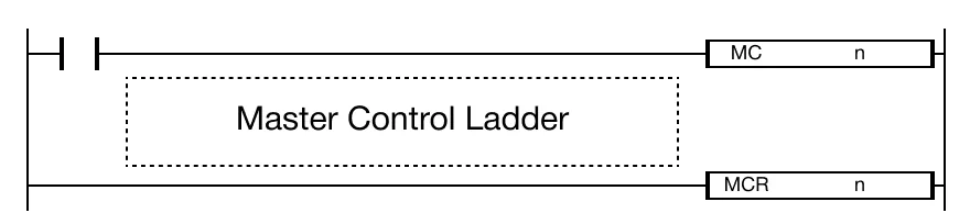
Ladder Diagram Examples
MCR

The MCR instruction declares the end of the Master Control area.
Example 1
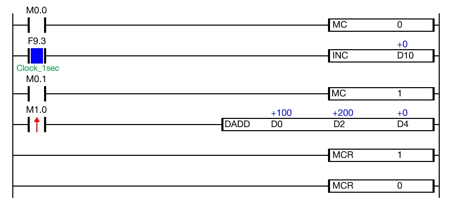
The Master Control area will execute the INC instruction every second if the contact, M0.0, is ON (1).
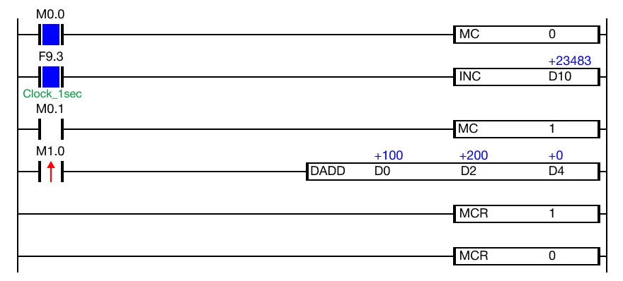
When the contact, M0.0, is powered ON (1), the INC instruction executes every second. Every execution condition within MC 0 ~ MCR 0 will execute until M0.0 is OFF (0).
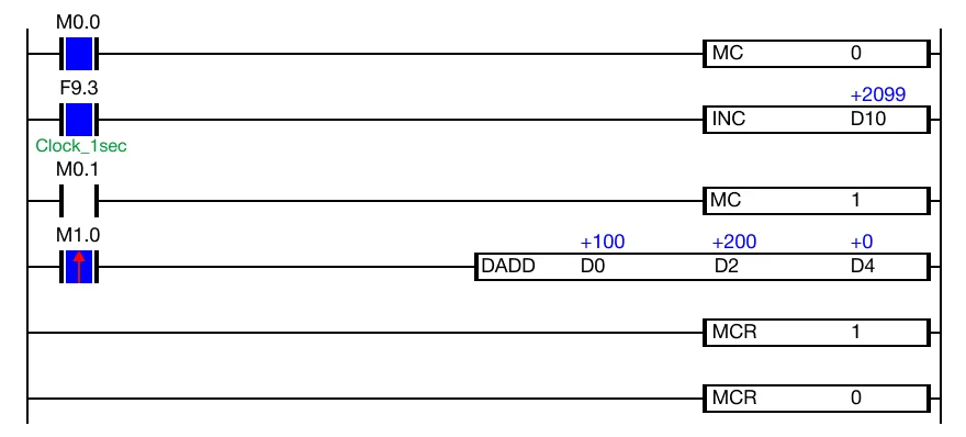
When the contact, M0.1, is OFF, MC 1 will NOT execute. Even though the contact, M1.0 is powered ON (1), the DADD instruction will NOT execute.
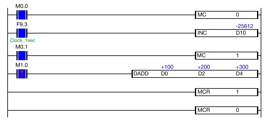
When the contact, M0.1, is powered ON (1), the DADD instruction will execute. Every execution condition within MC 1 ~ MCR 1 will execute until M0.1 is OFF (0).
Example 2
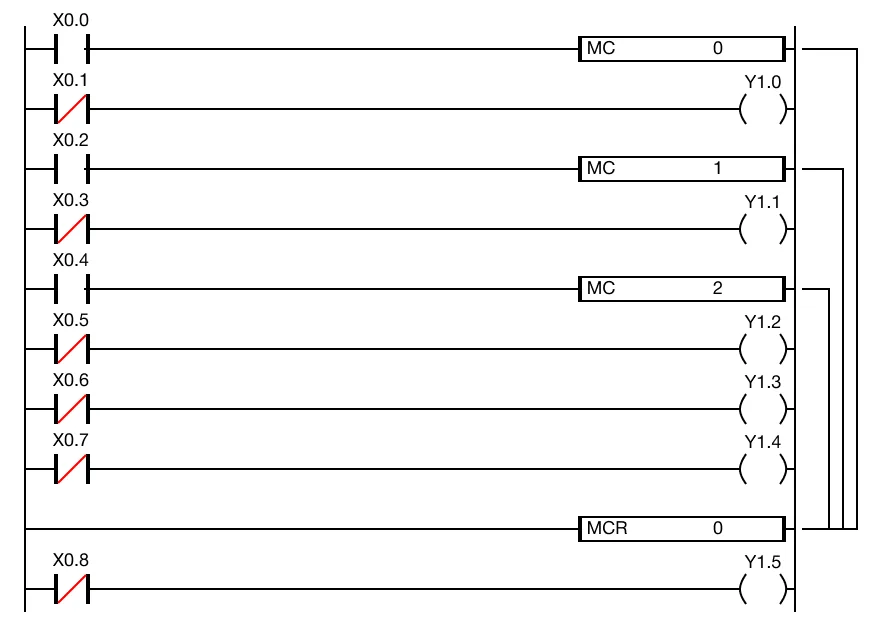
This example shows the lower to higher nesting order for the MC instruction where the MCR instruction terminates with the lowest possible value, 0.