Instruction Parameters
Supported PLC Series
| PLC-AES | PLC-FB | PLC-ES |
|---|---|---|
| ✓ | ✓ | ✓ |
Supported Data Registers
| M | X | Y | K | L | F | T | C | S | Z | R | Q | D | @D | Constant | |
|---|---|---|---|---|---|---|---|---|---|---|---|---|---|---|---|
| D | ✓ | – | ✓ | ✓ | ✓ | – | – | – | – | – | – | ✓ | ✓ | – | – |
Supported Flags
| Flag | Bit | Support |
|---|---|---|
| Error | F11.0 | – |
| Zero | F11.1 | – |
| Carry | F11.2 | – |
Number of Steps
| Steps |
|---|
| 1 |
Operands
| Operand | Description |
|---|---|
| D | The only operand. Entries are only BOOL data registers. This is the result to output on a falling edge. |
Notice
Instruction Behavior
The PLF instruction behaves as follows:
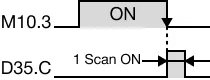
- When the execution condition goes from ON to OFF, the assigned data register, D, turns ON for 1 scan.
- When the execution does NOT change states or changed from OFF to ON, then the assigned data register, D, does NOT turn ON.
- Even if the RUN/STOP key switch is changed (RUN→STOP) after the execution of the PLF instruction, the instruction will NOT be executed again until the proper change of state of the executing statement from ON to OFF occurs.
Ladder Diagram Examples
PLF

The PLF instruction turns ON the assigned BOOL data register, D, for 1 scan when the execution condition goes from ON to OFF, or on the falling edge of the input signal.


When the contact, M10.5, is energized, the PLF instruction turns the bit, D35.C, ON (1) on the falling edge of the contact.