
Instruction Parameters
Supported PLC Series
| PLC-AES | PLC-FB | PLC-ES |
|---|---|---|
| ✓ | ✓ | ✓ |
Supported Data Registers
| M | X | Y | K | L | F | T | C | S | Z | R | Q | D | @D | Constant |
|---|---|---|---|---|---|---|---|---|---|---|---|---|---|---|
| – | – | – | – | – | – | – | – | – | – | – | – | – | – | – |
Supported Flags
| Flag | Bit | Support |
|---|---|---|
| Error | F11.0 | – |
| Zero | F11.1 | – |
| Carry | F11.2 | – |
Number of Steps
| Steps |
|---|
| 1 |
Notice
Notice
Compile errors occur under the following conditions:
- The STOP instruction is located in Interrupt Program, Subroutine Program, or the FOR ~ NEXT instructions.
Instruction Behavior
The STOP instruction behaves as follows:
- When the execution condition of the STOP instruction is powered ON (1), the STOP instruction resets the output, Y, and stops the PLC process.
- To restart the PLC process, change the RUN/STOP key switch from RUN→STOP→RUN.
- The STOP instruction should not be located in an Interrupt Program, Subroutine Program, or the FOR ~ NEXT instructions.
- If the STOP instruction is executed, it operates the same as changing the RUN/STOP key switch from RUN to STOP.
Operation Behavior
Operation of the STOP instruction according to the PLC:
- When the STOP instruction is operated with the CPU type such as PLC-ES, PLC-AES, PLC-FB:
- The scan program that includes the STOP instruction is executed until the END instruction and then the CPU mode changes, and no other scan programs are executed.
Ladder Diagram Examples
STOP

The STOP instruction stops execution of the PLC process and changes the PLC RUN/STOP mode from RUN→STOP.
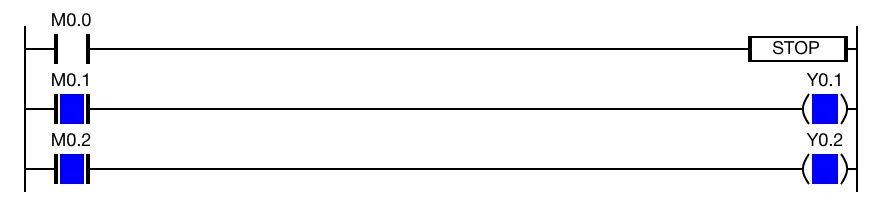
When the contacts, M0.1 and M0.2, are powered ON (1), the coils, Y0.1 and Y0.2, are energized.
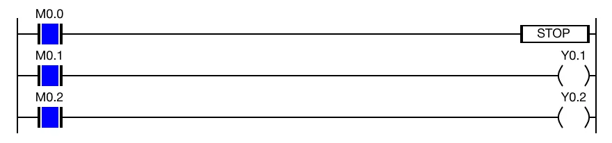
When the contact, M0.0, is powered ON (1), the coils the coils, Y0.1 and Y0.2, are deenergized while the STOP instruction is executing.