Modbus TCP Master Communication Program
Modbus TCP is a widely used communication protocol in industrial automation systems, designed to transmit data over Ethernet networks. It follows the client-server architecture where the Modbus Master (client) initiates communication by sending requests to connected devices, known as Modbus Slaves (servers). The Master controls the network, querying the Slaves for data or commanding actions. Each Slave responds to the Master’s request, providing data such as sensor readings, device status, or executing commands. Modbus TCP ensures reliable, real-time data exchange in various automation applications, enhancing system interoperability and efficiency.
This example will cover the Modbus TCP Master communication program.
Requirements and Assumptions:
- This example will use two PLC-ES PLCs on the same network.
- PLC-ES0806R (slave)
- IP Address: 192.168.1.223
- PLC-ES1616P with MOD-SENT01 (master)
- IP Address of MOD-SENT01: 192.168.1.224
- MOD-SENT01 is required for Modbus TCP Master communication and control unless using a PLC-AES Advanced CPU.
- PLC-ES0806R (slave)
- Both PLCs are on the same network with the same subnet mask and gateway.
- There are two communication methods:
- A network switch or hub must be used as a bridge between both PLCs.
- A straight-through Ethernet cable plugs into the slave PLC from an Ethernet switch, while another straight-through Ethernet cable plugs into the MOD-SENT01 (master).
- This example using this method.
- A straight-through Ethernet cable plugs into the slave PLC from an Ethernet switch, while another straight-through Ethernet cable plugs into the MOD-SENT01 (master).
- A crossover Ethernet cable must be used for direct PLC-PLC communication.
- A crossover Ethernet cable plugs into the slave PLC and the MOD-SENT01 (master).
- A network switch or hub must be used as a bridge between both PLCs.
Slave PLC
The following will occur on the PLC-0806R, which is the slave PLC.
Step 1: Create a new project.
Network Settings (PLC Parameters)
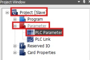
Step 2: In the Project Window, left-click Parameters to expand the parameters. Double-left-click PLC Parameters to open the PLC parameters window.
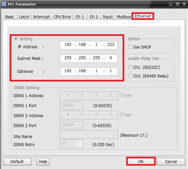
Step 3: Left-click Ethernet and change the network settings.
- The network settings for the slave PLC will be as follows:
- IP Address: 192.168.1.223
- Subnet Mask: 255.255.255.0
- Gateway: 192.168.1.1
Step 4: When finished, left-click OK.
Register Scan Program
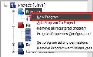
Step 5: Create a new scan program by right-clicking Program and left-clicking New Program.
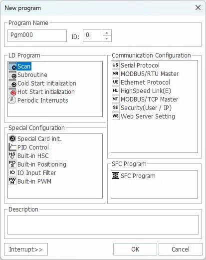
Step 6: Left-click Scan and left-click OK to continue.
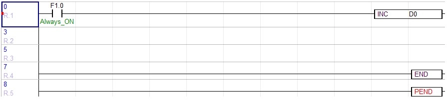
Step 7: Add the instruction to the scan program:
- Normally open contact with the Always ON internal flag, F1.0.
- This will execute the instruction, INC D0.
- For more information about the instruction, refer to the INC instruction.
- For every scan, 1 will be added to the data register D0.
- This will execute the instruction, INC D0.
Download Changes to the Slave

Step 8: Left-click the Download+ icon.
- Optionally, left-click Online and left-click Download.
This is all that is needed for the slave PLC.
Ping the Slave PLC (Optional)
If the slave PLC is connected to the same network as the computer, ping the IP to ensure the changes were downloaded.
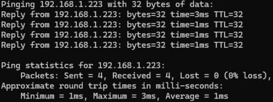
- Open a CMD prompt by typing cmd in the search bar on Windows.
- Type ping 192.168.1.223 or ping 192.168.1.223 -t for continuous transmission.
- If the PLC is not connected to the network, it will say, “Destination host unreachable.”
- The command prompt will say, “Reply from 192.168.1.223” if the PLC is connected to the network.
Master PLC
The following will occur on the PLC-ES1616P PLC and the MOD-SENT01 expansion module, which is the master.
Step 9: Create a new project. This will be separate from the slave PLC project.
Network Settings

Step 10: Connect to the PLC by left-clicking the Connect icon.
- Optionally, left-click Online and left-click Connect.
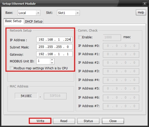
Step 11: In the Project Window, left-click to expand Card Properties. The MOD-SENT01 will now appear as Ethernet. Double-left-click Ethernet to configure the network settings.
Step 12: Configure the network settings. When finished, left-click Write.
- The network settings for the slave PLC will be as follows:
- IP Address: 192.168.1.224
- Subnet Mask: 255.255.255.0
- Gateway: 192.168.1.1
Step 13: Left-click the Disconnect icon.
- Optionally, left-click Online and left-click Disconnect.
Register Modbus TCP Master Special Program
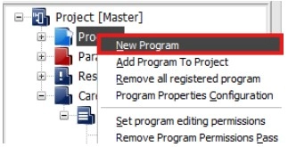
Step 14: Create a new Modbus TCP Master special program by right-clicking Program and left-clicking New Program.
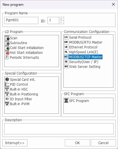
Step 15: Left-click MODBUS/TCP Master and left-click OK when finished.
Configure Modbus TCP Master Special Program
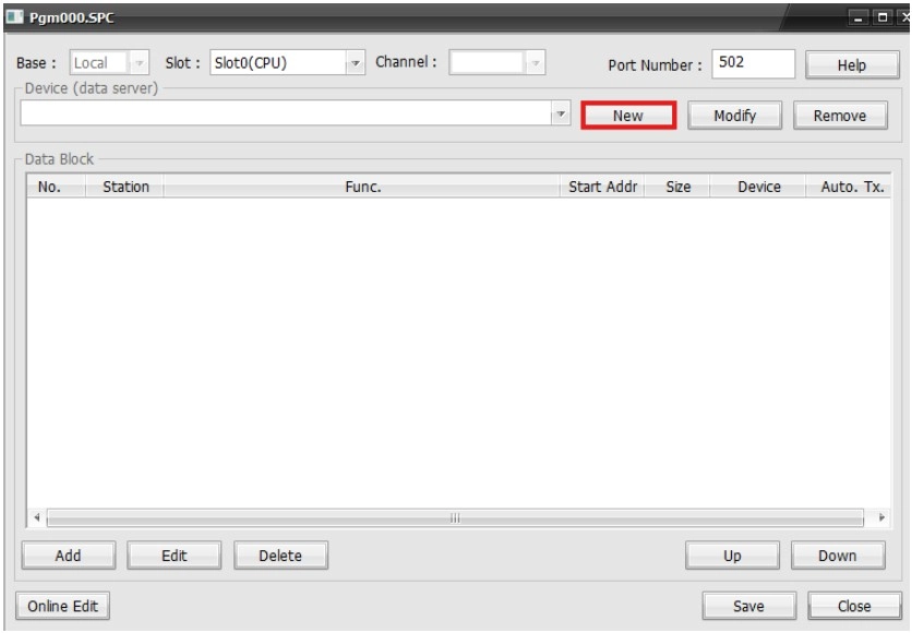
Step 16: In the Program Window, left-click New.
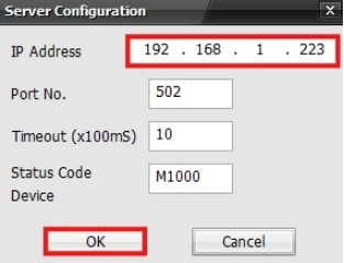
Step 17: Change the IP address to 192.168.1.223.
- This is the IP address of the slave PLC.
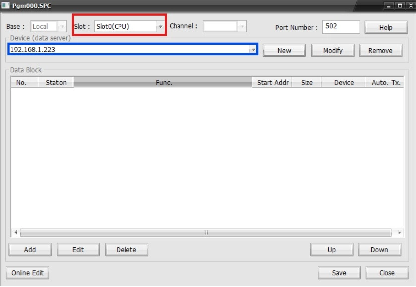
Step 18: Once the slave IP is correct, left-click Slot.
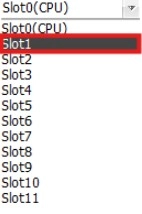
Step 19: Left-click the slot number that the MOD-SENT01 is positioned on the chassis.
- For this example, the MOD-SENT01 is the first expansion module, slot 1.
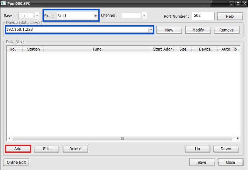
Step 20: Once the IP and slot number are correct, left-click Add to add a new slave.
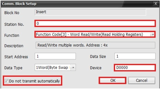
Step 21: Make the following changes and left-click OK when finished:
- Change the Function to Function Code[3].
- Change the Device to D0000.
- Toggle Do not transmit automatically.
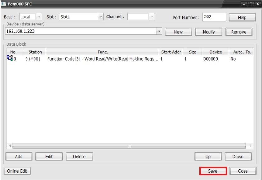
Step 22: Left-click Save.
Register Scan Program
Step 23: Create a new scan program by right-clicking Program and left-clicking New Program.
Step 24: Left-click Scan and left-click OK to continue.
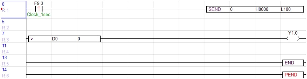
Step 25: Add the following instruction to the scan program:
- Positive Transition-Sensing Contact with a 1-second clock internal flag, F9.3.
- This will execute the instruction, SEND 0 H0000 L100.
- 0 is the program ID for the Modbus TCP special program.
- H0000 is the frame to send.
- L100 is a data register for any communication data from Modbus.
- For more information about the instruction, refer to the (SEND instruction).
- This will execute the instruction, SEND 0 H0000 L100.
Step 26: Add the following additional instruction to the scan program:
- Add the instruction > D0 0.
- This will energize the coil, Y1.0, every time D0 is greater than 0.
- For more information about the instruction, refer to the greater than (>) instruction.
- D0 is the data register being used in the slave program.
- It is now accessible via Modbus in the master program.
- This will energize the coil, Y1.0, every time D0 is greater than 0.
Download Changes to the Master
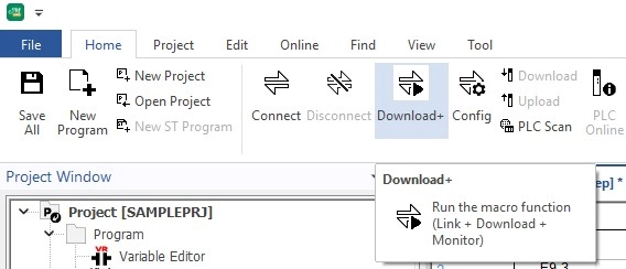
Step 27: Left-click the Download icon.
- Optionally, left-click Online and left-click Link+Download+Monitor.
This is all that is needed for the master PLC.
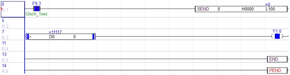
- The value of D0 will change, meaning the value is being read from the slave PLC.
- When the coil, Y1.0, is OFF, D0 is less than 0.
Ping the Master PLC (Optional)
- If the master PLC is connected to the same network as the computer, ping the IP to ensure the changes were downloaded.
- Open a CMD prompt by typing cmd in the search bar on Windows.
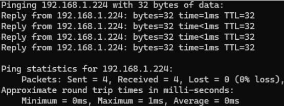
- Type ping 192.168.1.224 or ping 192.168.1.224 -t for continuous transmission.
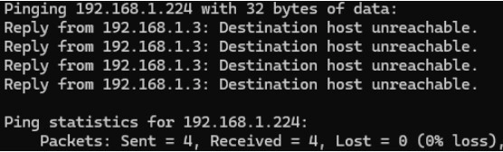
- If the PLC is not connected to the network, it will say, “Destination host unreachable.”