
Configuration
Step 1: In the menu bar, left click Home and left click New Project.
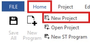
Optionally, in the menu bar left click File and left click New Project.
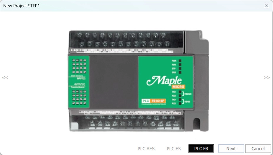
Step 2: Left click PLC-FB and then left click next.
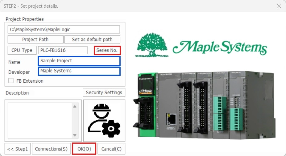
Step 3: Left-click Series No. to change from PLC-FB0808 to PLC-FB1616.
Step 4: Left-click OK.
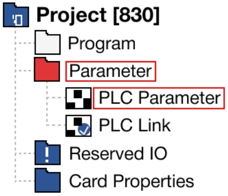
Step 5: In the Project Window, expand Parameter and double left click PLC Parameter.
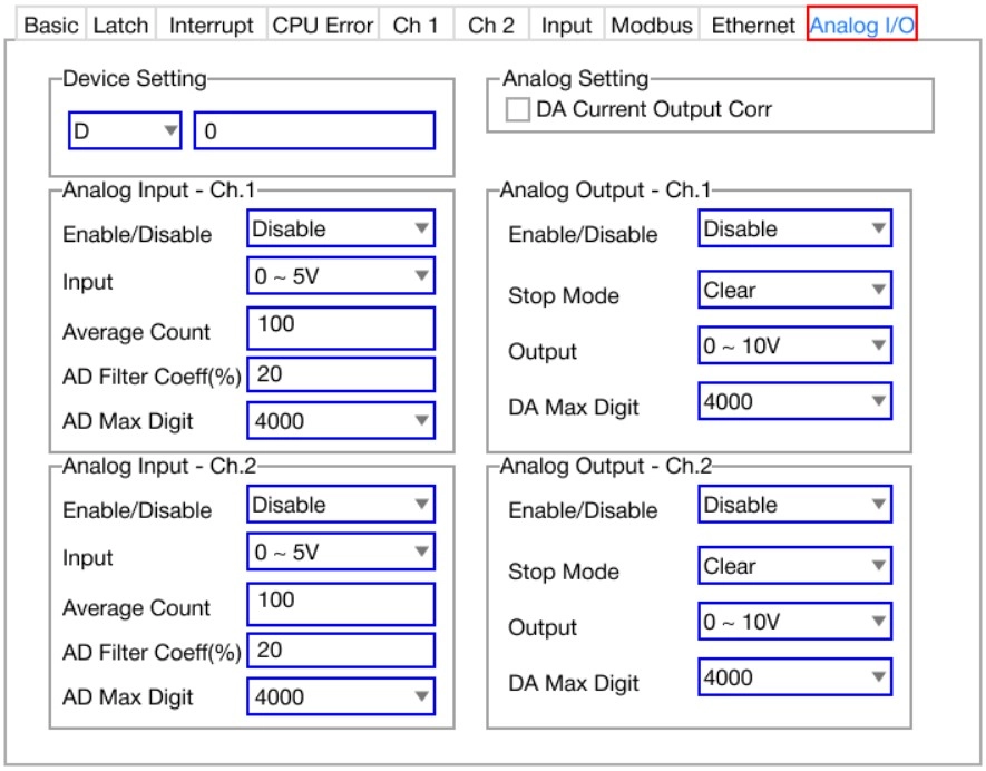
Step 6: In the PLC Parameter window, left click Analog I/O.
- Channel 1 and channel 2 can be configured here.
- The Device Setting option will be the starting data register type and number for all analog operations.
Device Setting
- The device setting designated the starting data register address where the analog value is updated.
- 20 WORDs are occupied from the starting data register address.
- Each WORD can read or write data.
- The remaining offsets not mentioned in the table below are not used.
Enable/Disable
- To enable the channel for analog input/output, set the value to enabled.
- To disable the channel for analog input/output, set the value to disabled.
Input
- The input signal range sets the range for voltage or current input.
- The ranges are as follows:
- Voltage:
- 0V ~ +5V
- 0V ~ +10V
- +1V ~ +5V
- +1V ~ +10V
- Current:
- 0mA ~ 20mA
- 4mA ~ 20mA
- Voltage:
Average Count
- If the analog input value can be filtered by the moving window filtering feature, it is possible to set the number of sampling data in the average count field
- The number of samples can range from 1 ~ 255.
- If the averaging count is set to 0, the moving window filtering feature is disabled.
AD Filter Coefficient (%)
- This is used to set the AD filter coefficient percentage.
AD Max Digit
- This is the maximum digital value for the analog input.
Stop Mode
- If the value of the stop value mode is set to hold, the value will be retained when the PLC is switched to STOP mode.
- If the value of the stop mode is set to clear, the value will NOT be retained when the PLC is switched to STOP mode.
Output
- The output signal range sets the range for voltage or current output.
- The ranges are as follows:
- Voltage: 0V ~ +10V
- Current: 4mA ~ 20mA
DA Max Digit
- This is the maximum digital value from the output.
Analog Data Register Offset
- After selecting the starting data register, the following offsets are used to read/write values:
| Offset | Description | Range | Read | Write |
|---|---|---|---|---|
| 0 | Channel 1 AD Input Value | 0 ~ 4,000 (16,000 SW) | ✓ | – |
| 1 | Channel 2 AD Input Value | 0 ~ 4,000 (16,000 SW) | ✓ | – |
| 2 | Channel 1 DA Output Value | 0 ~ 4,000 (16,000 SW) | ✓ | ✓ |
| 3 | Channel 2 DA Output Value | 0 ~ 4,000 (16,000 SW) | ✓ | ✓ |
| 4 | Error Code | Refer here | ✓ | – |
| 5 | Channel 1 AD Measured Value | Depends on configuration | ✓ | – |
| 6 | Channel 2 AD Measured Value | Depends on configuration | ✓ | – |
| 7 | Channel 1 AD Percentage Value | 0 ~ 1,000 (0% ~ 100%) | ✓ | – |
| 8 | Channel 2 AD Percentage Value | 0 ~ 1,000 (0% ~ 100%) | ✓ | – |
| 9 | Reserved | – | – | – |
| 10 | Channel 1 DA Signal Value | Depends on configuration | ✓ | – |
| 11 | Channel 2 DA Signal Value | Depends on configuration | ✓ | – |
| 12 | Reserved | – | – | – |
| 13 | Reserved | – | – | – |
| 14 | Reserved | – | – | – |
| 15 | Reserved | – | – | – |
| 16 | Reserved | – | – | – |
| 17 | Reserved | – | – | – |
| 18 | Reserved | – | – | – |
| 19 | Reserved | – | – | – |
Error
| Error Code | Description |
|---|---|
| 1 | Input Type Error |
| 2 | Output Type Error |
| 3 | AD Disconnection Error +1V ~ +5V/+10V: Less than 0.2V 4mA ~ 20mA: Less than 0.8mA |
AD Measured Value
- This displays the measured analog value according to the range configuration.
| Input Range | Minimum Value | Maximum Value |
|---|---|---|
| 0V ~ +5V | 0 | 500 |
| 0V ~ +10V | 0 | 1,000 |
| +1V ~ +5V | 100 | 500 |
| +1V ~ +10V | 100 | 1,000 |
| 0mA ~ 20mA | 0 | 2,000 |
| 4mA ~ 20mA | 400 | 2,000 |
DA Signal Value
- This displays the DA output value according to the range and the voltage/current configuration.
| Output Range | Minimum Value | Maximum Value |
|---|---|---|
| 0V ~ +10V | 0 | 1,000 |
| 4mA ~ 20mA | 400 | 2,000 |
Switch Configuration
The PLC-FB1616 series has two sets of switches on either side of the serial communication port.
- The switch on the right is the important switch.
- To measure current for either channel 1 or 2, flip respective the switch up (I)
- To measure voltage for either channel 1 or 2, flip respective the switch down (V).