
IO-SA0202Y Internal I/O Table
| Input | Name of Signal | Output | Name of Signal |
|---|---|---|---|
| Xn.0 | AD Module Ready | Yn.0 | Reserved |
| Xn.1 | Reserved | Yn.1 | Reserved |
| Xn.2 | Flag indicating the operation condition setup | Yn.2 | Requesting to set up an operation condition |
| Xn.3 | Channel 1 High Alarm Value | Yn.3 | DA Channel 1 Output Enable |
| Xn.4 | Channel 2 High Alarm Value | Yn.4 | DA Channel 2 Output Enable |
| Xn.5 | Channel 1 Low Alarm Value | Yn.5 | Reserved |
| Xn.6 | Channel 2 Low Alarm Value | Yn.6 | Reserved |
| Xn.7 | Channel 1 Maximum Alarm Value | Yn.7 | Reserved |
| Xn.8 | Channel 2 Maximum Alarm Value | Yn.8 | Reserved |
| Xn.9 | Reserved | Yn.9 | Reserved |
| Xn.A | Reserved | Yn.A | Reserved |
| Xn.B | Reserved | Yn.B | Reserved |
| Xn.C | Reserved | Yn.C | Reserved |
| Xn.D | Reserved | Yn.D | Reserved |
| Xn.E | Reserved | Yn.E | Reserved |
| Xn.F | AD Module Error Flag | Yn.F | Requesting to Clear Error Flag |
Allocation Example
The IO-SA0202Y is allocated one WORD of X (Xn.0 ~ Xn.F) and one WORD of Y (Yn.0 ~ Yn.F).
n is a number representing the IO-SA0202Y‘s position within the chassis.
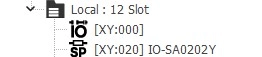
To access the X memory registers for the IO-SA0202Y, the X value range is X2.0 ~ X2.F.
To access the Y memory registers for the IO-SA0202Y, the Y value range is Y2.0 ~ Y2.F.