
PWM Parameters
| Memory Address (Hexadecimal) | Memory Address (Decimal) | Details | Read | Write |
|---|---|---|---|---|
| 00H | 0 | PWM Output Enable | ✓ | ✓ |
| 01H | 1 | Frequency 1, 2, 3, and 4 | ✓ | ✓ |
| 02H | 2 | Frequency 5, 6, 7, and 8 | ✓ | ✓ |
| 03H | 3 | Frequency 9, 10, 11, and 12 | ✓ | ✓ |
| 04H | 4 | Reserved | – | – |
| 05H | 5 | Frequency RAMP Control Time Channels 1, 2, 3, and 4 | ✓ | ✓ |
| 06H | 6 | Frequency RAMP Control Time Channels 5, 6, 7, and 8 | ✓ | ✓ |
| 07H | 7 | Frequency RAMP Control Time Channels 9, 10, 11, and 12 | ✓ | ✓ |
| 08H | 8 | Reserved | – | – |
| 09H | 9 | Error Code | ✓ | ✓ |
| 0AH | 10 | Channel 1 DUTY Cycle Ration | ✓ | ✓ |
| 0BH | 11 | Channel 2 DUTY Cycle Ration | ✓ | ✓ |
| 0CH | 12 | Channel 3 DUTY Cycle Ration | ✓ | ✓ |
| 0DH | 13 | Channel 4 DUTY Cycle Ration | ✓ | ✓ |
| 0EH | 14 | Channel 5 DUTY Cycle Ration | ✓ | ✓ |
| 0FH | 15 | Channel 6 DUTY Cycle Ration | ✓ | ✓ |
| 10H | 16 | Channel 7 DUTY Cycle Ration | ✓ | ✓ |
| 11H | 17 | Channel 8 DUTY Cycle Ration | ✓ | ✓ |
| 12H | 18 | Channel 9 DUTY Cycle Ration | ✓ | ✓ |
| 13H | 19 | Channel 10 DUTY Cycle Ration | ✓ | ✓ |
| 14H | 20 | Channel 11 DUTY Cycle Ration | ✓ | ✓ |
| 15H | 21 | Channel 12 DUTY Cycle Ration | ✓ | ✓ |
| 16H | 22 | Reserved | – | – |
| 17H | 23 | Reserved | – | – |
| 18H | 24 | Reserved | – | – |
| 19H | 25 | Reserved | – | – |
| 1AH | 26 | Reserved | – | – |
| 1BH | 27 | Reserved | – | – |
| 1CH | 28 | Reserved | – | – |
| 1DH | 29 | Reserved | – | – |
| 1EH | 30 | Channel 1 DUTY Cycle RAMP Time (× 10ms) | ✓ | ✓ |
| 1FH | 31 | Channel 2 DUTY Cycle RAMP Time (× 10ms) | ✓ | ✓ |
| 20H | 32 | Channel 3 DUTY Cycle RAMP Time (× 10ms) | ✓ | ✓ |
| 21H | 33 | Channel 4 DUTY Cycle RAMP Time (× 10ms) | ✓ | ✓ |
| 22H | 34 | Channel 5 DUTY Cycle RAMP Time (× 10ms) | ✓ | ✓ |
| 23H | 35 | Channel 6 DUTY Cycle RAMP Time (× 10ms) | ✓ | ✓ |
| 24H | 36 | Channel 7 DUTY Cycle RAMP Time (× 10ms) | ✓ | ✓ |
| 25H | 37 | Channel 8 DUTY Cycle RAMP Time (× 10ms) | ✓ | ✓ |
| 26H | 38 | Channel 9 DUTY Cycle RAMP Time (× 10ms) | ✓ | ✓ |
| 27H | 39 | Channel 10 DUTY Cycle RAMP Time (× 10ms) | ✓ | ✓ |
| 28H | 40 | Channel 11 DUTY Cycle RAMP Time (× 10ms) | ✓ | ✓ |
| 29H | 41 | Channel 12 DUTY Cycle RAMP Time (× 10ms) | ✓ | ✓ |
| 2AH | 42 | Reserved | – | – |
| 2BH | 43 | Reserved | – | – |
| 2CH | 44 | Reserved | – | – |
| 2DH | 45 | Reserved | – | – |
| 2EH | 46 | Reserved | – | – |
| 2FH | 47 | Reserved | – | – |
| 30H | 48 | Reserved | – | – |
| 31H | 49 | Reserved | – | – |
| 32H | 50 | Reserved | – | – |
| 33H | 51 | Reserved | – | – |
| 34H | 52 | Reserved | – | – |
| 35H | 53 | Reserved | – | – |
| 36H | 54 | Reserved | – | – |
| 37H | 55 | Reserved | – | – |
| 38H | 56 | Reserved | – | – |
| 39H | 57 | Reserved | – | – |
| 3AH | 58 | Reserved | – | – |
| 3BH | 59 | Reserved | – | – |
| 3CH | 60 | Reserved | – | – |
| 3DH | 61 | Reserved | – | – |
| 3EH | 62 | Reserved | – | – |
| 3FH | 63 | OS Version | – | – |
Pulse-Width Modulation Output Enable
- The pulse-width modulation output enable will enable the channels for pulse-width modulation when set to 1 or general digital output when set to 0.
- The PWM output function can be enabled by using the TO instruction.
| Buffer Memory | Bit 0 | Bit 1 | Bit 2 | Bit 3 | Bit 4 | Bit 5 | Bit 6 | Bit 7 | Bit 8 | Bit 9 | Bit 10 | Bit 11 | Bit 12 | Bit 13 | Bit 14 | Bit 15 |
|---|---|---|---|---|---|---|---|---|---|---|---|---|---|---|---|---|
| Channel Number | CH 1 | CH 2 | CH 3 | CH 4 | CH 5 | CH 6 | CH 7 | CH 8 | CH 9 | CH 10 | CH 11 | CH 12 | X | X | X | X |
Frequency Control
- The pulse-width modulation supports functions to control the frequency range from 0~4,000pps.
- 4 channels per group can be controlled.
- A total of 3 groups can be controlled.
- 4 channels per group can be controlled.
- The frequencies of each group are set by the TO instruction.
| Frequency A or General Digital Output | Frequency B or General Digital Output | Frequency C or General Digital Output |
|---|---|---|
| Channel 1 (Yn.2) | Channel 5 (Yn.A) | Channel 9 (Yn + 1.2) |
| Channel 2 (Yn.3) | Channel 6 (Yn.B) | Channel 10 (Yn + 1.3) |
| Channel 3 (Yn.6) | Channel 7 (Yn.C) | Channel 11 (Yn + 1.4) |
| Channel 4 (Yn.7) | Channel 8 (Yn.D) | Channel 12 (Yn + 1.5) |
- Every 4 PWM output included in a group are operated in the same frequency.
- 3 different frequency outputs are available at the same time since 3 groups are offered.
- When the TO instruction is operated on the buffer memory, the output terminal outputs the designated frequency instantly.
- To prevent a sharp change of frequency, refer to frequency RAMP control.
- If the frequency value is over 4,000pps, both the valid range of the DUTY cycle and degree of precision are decreased
| Frequency (pps) | Minimum Value of DUTY Cycle (%) | Maximum Value of DUTY Cycle (%) |
|---|---|---|
| 5,000 | 1.0 | 98.0 |
| 10,000 | 1.5 | 95.0 |
| 15,000 | 3.0 | 94.0 |
| 20,000 | 4.0 | 93.0 |
| 25,000 | 5.0 | 91.0 |
| 30,000 | 6.0 | 89.0 |
| 35,000 | 7.0 | 87.0 |
| 40,000 | 9.0 | 85.0 |
| 45,000 | 10.0 | 83.0 |
| 50,000 | 12.0 | 82.0 |
| 55,000 | 13.0 | 80.0 |
| 60,000 | 14.0 | 78.0 |
| 65,000 | 15.0 | 75.0 |
RAMP Control
- RAMP control can be used to prevent a sharp change of the frequency and DUTY cycle.
- The output will be gradually changed during the RAMP control time, which the value of the frequency or DUTY cycle have configured.
- When the set value of the RAMP control time of buffer memory is 0, output will be changed immediately.
- The following is a method for RAMP control:
- Change the RAMP control time before the value to control as intended.
- In case of a power reset or CPU STOP during the RAMP operation, reset the value again by using the TO instruction.
- he value of the buffer memory will be set back to the initial value, 0.
Frequency RAMP Control Time
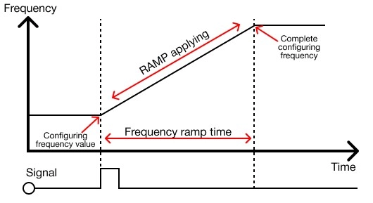
- The frequency will be changed through the set RAMP control time when the frequency value is changed after setting the frequency RAMP control time.
- The frequency RAMP control time can be set by using the TO instruction.
- In case the frequency RAMP control time is changed during the RAMP operation, it will be applied to the NEXT RAMP operation.
- In case of a power reset or CPU STOP during the RAMP operation, reset the value again by using the TO instruction.
Controlling DUTY Cycle
- The pulse-width modulation supports functions to control the DUTY cycle 0.0% ~ 100.0% within 1/1,000 resolution.
- The DUTY cycles are able to be controlled per channel for a total of 12 channels.
- The DUTY cycle can be set using the TO instruction.
- When the TO instruction is operated, the output terminal will be configured to set the DUTY cycle and being output.
- To prevent a sharp change of frequency, refer to frequency RAMP control.
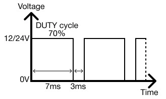
- If the digital signal of +12V-+24V voltage is set to the DUTY cycle 70.0% (as shown above), the voltage output of +8.4V-+16.8V in average is available.
- The DUTY cycle control (PWM) can be utilized in various ways of substituting an analog signal.
- Controlling the speed of a motor, switch, or ratio of a value are examples.
DUTY Cycle RAMP Control
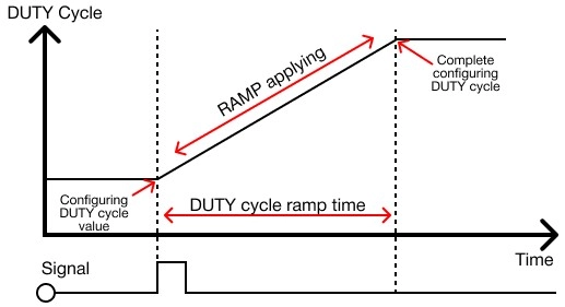
- If the DUTY cycle’s value is configured after setting the DUTY cycle RAMP control time, the DUTY cycle will be gradually changed during the set RAMP control time.
- The DUTY cycle ratio can be set using the TO instruction.
- In case the DUTY cycle ramp control time is configured during the AMP operation, it will be applied to the NEXT RAMP operation.
- In case of a power reset or CPU STOP during the RAMP operation, reset the value again by using the TO instruction.
- The value of the buffer memory will be set back to the initial value, 0.