Instruction Parameters
Supported PLC Series
| PLC-AES | PLC-FB | PLC-ES |
|---|---|---|
| ✓ | ✓ | ✓ |
Supported Data Registers
| M | X | Y | K | L | F | T | C | S | Z | R | Q | D | @D | Constant | |
|---|---|---|---|---|---|---|---|---|---|---|---|---|---|---|---|
| c | – | – | – | – | – | – | – | ✓ | – | – | – | ✓ | – | – | – |
| v | – | – | – | – | – | – | – | – | – | ✓ | – | – | ✓ | – | ✓ |
Supported Flags
| Flag | Bit | Support |
|---|---|---|
| Error | F11.0 | ✓ |
| Zero | F11.1 | – |
| Carry | F11.2 | – |
Number of Steps
| Steps |
|---|
| 3 |
Operands
| Operand | Description |
|---|---|
| c | The first operand. Entries are only counter data registers. |
| v | The second operand. Entries are unsigned WORD data registers or constants. This is the value the counter value, c, will be reset to. The unsigned value range is 0 ~ 65,535 (216-1). The Hexadecimal value range is H0000 ~ HFFFF. Signed value entries will be treated as unsigned values. |
Notice
Error Flag (F11.0) Notice
The error flag, F11.0, will be ON for one scan when the address of the data register assigned by Z exceeds its range. The valid range of the data register Z is Z128 ~ Z1023 when using Function Block implementation. F11.0 turns ON when the value of the data register, CC, exceeds the range of 0 ~ 65,535 (unsigned).
Instruction Behavior
The CTD instruction behaves as follows:
- The data register C assigned to c is a BOOL data register.
- CS and CC express the detailed value of the data register C assigned to c.
- CC is a WORD data register used for the current count value of c.
- CS is a WORD data register used for the count setting value of c.
- The value of CS is equal to the value of v.
- CS and CC express the detailed value of the data register C assigned to c.
- The value of CC decreases each time the instruction is energized.
- The counter contact c turns ON when the value of CC is equal to 0.
- The counter contact c will remain ON as long as CC is equal to 0 only.
- If the value of CC is 0, the instruction will not continue executing.
- If the reset signal is energized, CC will reset to v.
- The counter contact c will turn OFF.
- The counter contact c turns ON when the value of CC is equal to 0.
- The counter contact assigned to c can be used as an A or B contact.
- When the counter contact meets the RST instruction, the contact is turned OFF (0), but the value of CC is maintained.
Ladder Diagram Examples
CTD
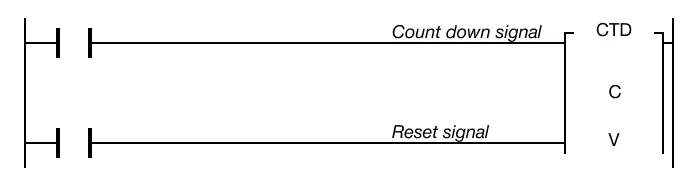
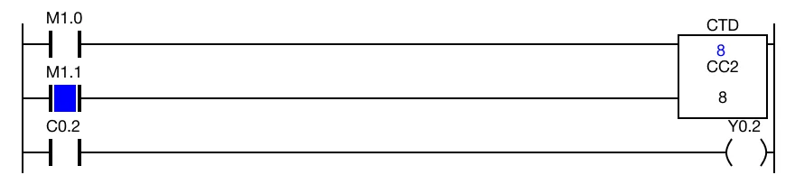
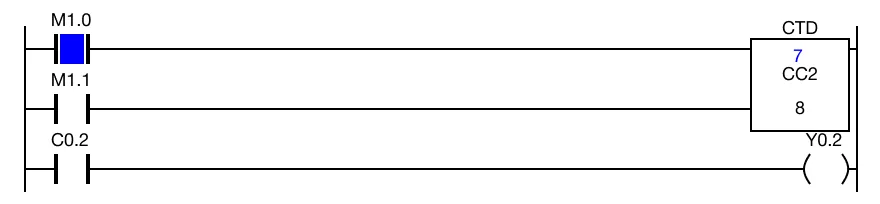
The CTD instruction starts from the value v, and counts down to 0. The count number is saved in a counter data register, CC. If the value of CC is equal to 0, the counter contact, C, energizes.
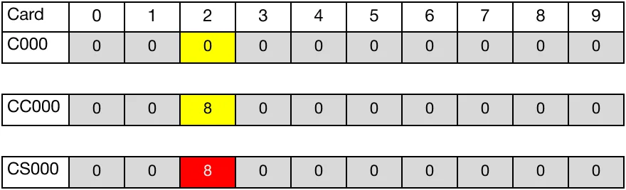
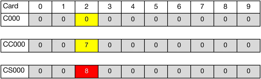
The initial value of the BOOL counter data register, C0.0, is 0. The initial value of the WORD current count data register, CC0.0, is 8. The initial value of the WORD set count data register, CS0.0, is 8.
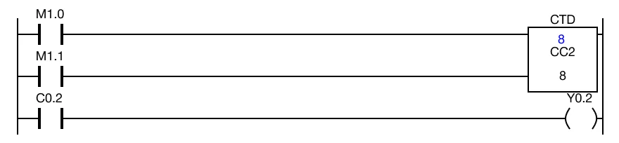
When the contact, M1.0, is powered ON (1), the counter instruction counts down by 1, decreasing the current count data register, CC0.0, to 7.

When the contact, M1.0, is powered ON (1) again, the counter instruction counts down by 1, decreasing the current count data register, CC0.0, to 1.
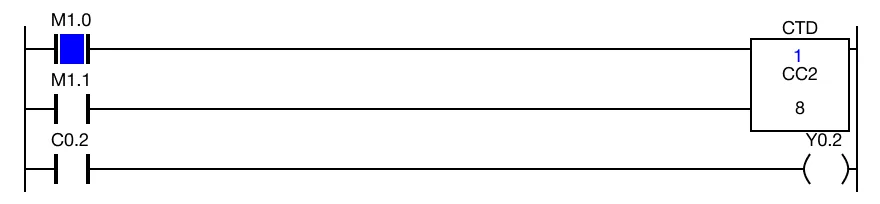
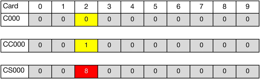
When the contact, M1.0, is powered ON (1) again, the counter instruction counts down by 1, decreasing the current count data register, CC0.0, to 0.
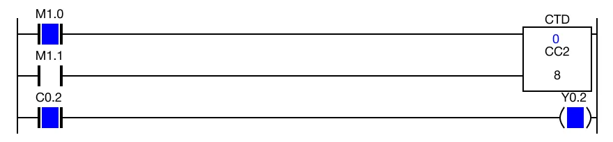
Since CC0.0 is equal to CS0.0, the BOOL counter data register, C0.0, is set to 1. As a result, the coil, Y0.2, is energized.
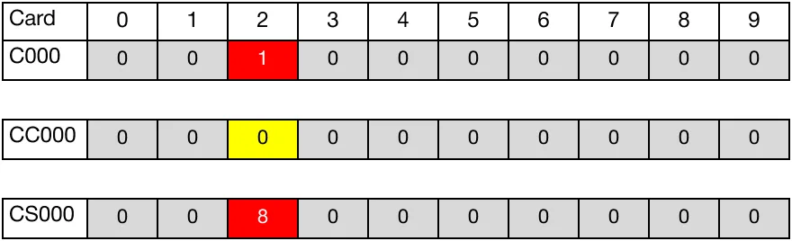
When the contact, M1.1, is powered ON (1), the value the current count data register, CC0.0, resets to 8. Since CC0.00 is greater than CS10, the BOOL counter data register, C0.0, is set to 0. As a result, the coil, Y0.2, is deenergized.