Instruction Parameters
Supported PLC Series
| PLC-AES | PLC-FB | PLC-ES |
|---|---|---|
| ✓ | ✓ | ✓ |
Supported Data Registers
| M | X | Y | K | L | F | T | C | S | Z | R | Q | D | @D | Constant | |
|---|---|---|---|---|---|---|---|---|---|---|---|---|---|---|---|
| S1 | ✓ | ✓ | ✓ | ✓ | ✓ | ✓ | ✓ | ✓ | – | ✓ | ✓ | ✓ | ✓ | ✓ | ✓ |
| S2 | ✓ | ✓ | ✓ | ✓ | ✓ | ✓ | ✓ | ✓ | – | ✓ | ✓ | ✓ | ✓ | ✓ | – |
| D | ✓ | – | ✓ | ✓ | ✓ | – | – | – | – | ✓ | ✓ | ✓ | ✓ | ✓ | – |
| B | ✓ | ✓ | ✓ | ✓ | ✓ | ✓ | ✓ | ✓ | – | ✓ | ✓ | ✓ | ✓ | ✓ | ✓ |
| n | ✓ | ✓ | ✓ | ✓ | ✓ | ✓ | ✓ | ✓ | – | ✓ | ✓ | ✓ | ✓ | ✓ | ✓ |
Supported Flags
| Flag | Bit | Support |
|---|---|---|
| Error | F11.0 | ✓ |
| Zero | F11.1 | – |
| Carry | F11.2 | – |
Number of Steps
| Steps |
|---|
| 6 |
Operands
| Operand | Description |
|---|---|
| S1 | The first operand. Entries are WORD data registers or constants. This is the starting data register for the first range of n data registers to compare to S2. This requires n data registers. The signed value range is -32,768 ~ 32,767 (216). The Hexadecimal value range is H0000 ~ HFFFF. |
| S2 | The second operand. Entries are only WORD data registers. This is the starting data register for the second range of n data registers to compare to S1. This requires n data registers. The signed value range is -32,768 ~ 32,767 (216). The Hexadecimal value range is H0000 ~ HFFFF. |
| D | The third operand. Entries are only WORD data registers. This is where the comparison result is saved. This could require more than 1 WORD data register. |
| B | The fourth operand. Entries are BOOL data registers or constants. This is the starting bit address to save the comparison results to. |
| n | The fifth operand. Entries are WORD data registers or constants. This is the amount of data registers to compare starting at S1 and S2. |
Notice
Error Flag (F11.0) Notice
The error flag, F11.0, will be ON for one scan when the address of the data register assigned by @D exceeds the range of the data register, D. The range of the data register, D, is dependent on the CPU type.
Ladder Diagram Examples
BK>=
The BK>= instruction compares n number of WORD data registers starting at S1 to n number of WORD data registers starting at S2. For each data register in the range S1 ~ Sn that is greater than or equal to each data register in the range S2 ~ Sn, the corresponding bit in the data register D, starting at bit number B, will turn ON (1).

 = instruction will compare the following expressions for a true or false value:”/>
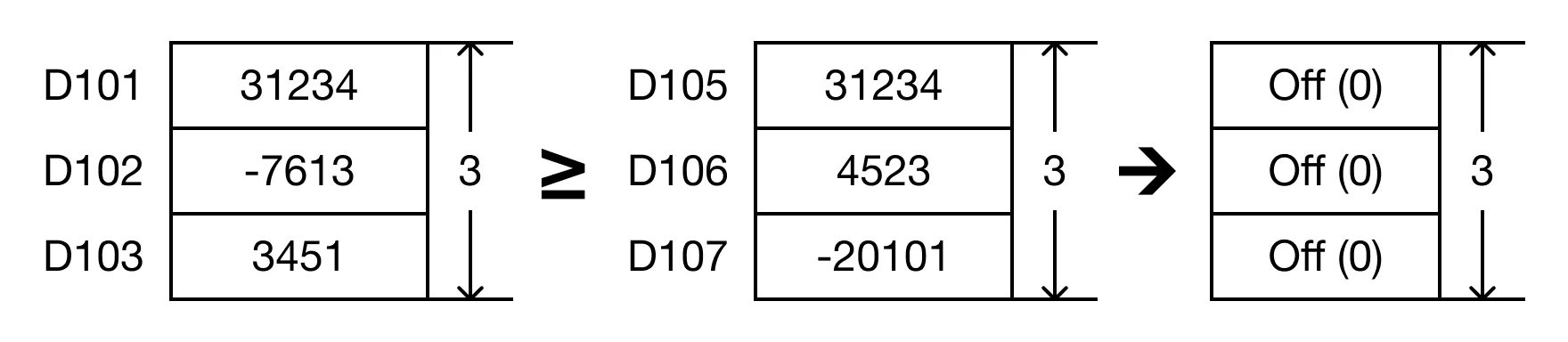
- The BK>= instruction will compare the following expressions for a true or false value:
- D101 ≥ D105 → 31,234 ≥ 31,234
- D102 ≥ D106 → -7,613 ≥ 4,523
- D103 ≥ D107 → 3,451 ≥ -20,101

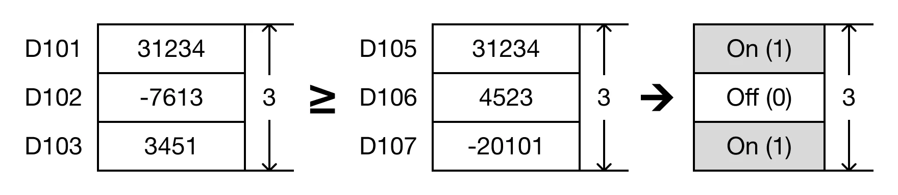
- When the open contact, M0.0, is powered ON (1), the values of the data registers are compared.
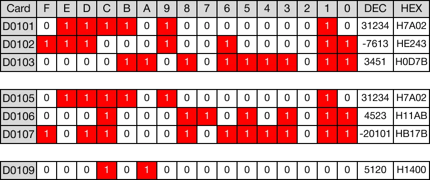
- D101 ≥ D105 → 31,234 ≥ 31,234 (TRUE → D109.A = 1)
- D102 ≥ D106 → -7,613 ≥ 4,523 (FALSE → D109.B = 0)
- D103 ≥ D107 → 3,451 ≥ -20,101 (TRUE → D109.C = 1)
Memory Monitor
 =P instruction compares n number of WORD data registers starting at S1 to n number of WORD data registers starting at S2.”/>
BK>=P
The BK>=P instruction compares n number of WORD data registers starting at S1 to n number of WORD data registers starting at S2. For each data register in the range S1 ~ Sn that is greater than or equal to each data register in the range S2 ~ Sn, the corresponding bit in the data register D, starting at bit number B, will turn ON (1). Every time this instruction executes, it energizes the output only once.

 =P instruction will compare the following expressions for a true or false value:”/>
- The BK>=P instruction will compare the following expressions for a true or false value:
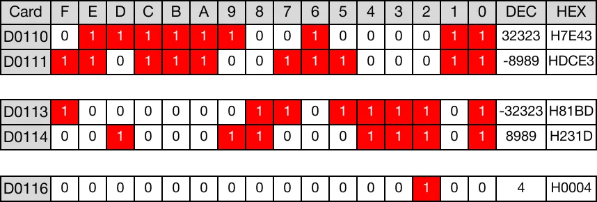
- D110 ≥ D113 → 32,323 ≥ -32,323
- D111 ≥ D114 → -8,989 ≥ 8,989


- When the open contact, M0.1, is powered ON (1), the values of the data registers are compared.
- D110 ≥ D113 → 32,323 ≥ -32,323 (TRUE → D116.2 = 1)
- D111 ≥ D114 → -8,989 ≥ 8,989 (FALSE → D116.3 = 0)
Memory Monitor