
Modular CPU Series General Specifications
Temperature
| Specification | Description |
|---|---|
| Operating Temperature | -10°C ~ 65°C 14°F ~ 149°F |
| Storage Temperature | -25°C ~ 80°C -13°F ~ 176°F |
Operating Humidity
| Specification | Description |
|---|---|
| Operating Humidity | 5% ~ 95% RH, Non-condensing |
| Storage Humidity | 5% ~ 95% RH, Non-condensing |
Vibration
Standards used: IEC 61131-2.
Intermittent Vibration
| Frequency | Acceleration | Amplitude | Times |
|---|---|---|---|
| 5Hz ≤ f < 9Hz | – | 3.5mm | 10 times in X, Y, and Z |
| 9Hz ≤ f ≤ 150Hz | 9.8m/s2 (1G) | – | 10 times in X, Y, and Z |
Continuous Vibration
| Frequency | Acceleration | Amplitude | Times |
|---|---|---|---|
| 5Hz ≤ f < 9Hz | – | 1.75mm | 10 times in X, Y, and Z |
| 9Hz ≤ f ≤ 150Hz | 4.9m/s2 (0.5G) | – | 10 times in X, Y, and Z |
Shocks
| Description | Standard |
|---|---|
| • Maximum Shock Acceleration: 147m/s2 (15G) • Time: 11ms • Pulse Wave: Sine Half-Wave (3 times in X, Y, Z) | IEC 61131-2 |
Noise
Square Wave Impulse Noise
| Square Wave Impulse Noise | ±2kV |
Electrostatic Discharge
| Electrostatic Discharge | Voltage: 4kV (contact) 8kV (air) | IEC 61131-2 IEC 61000-4-2 |
Radiated Electromagnetic Field
| Radiated Electromagnetic Field | 80MHz ~ 1,000MHz 10V/m | IEC 61131-2 IEC61000-4-3 |
Fast Transient Burst Noise (Voltage)
| CPU Power | 2kV | IEC 61131-2 IEC 61000-4-4 |
| Digital/Analog I/O (AC) | 2kV | IEC 61131-2 IEC 61000-4-4 |
| Digital/Analog I/O (DC) | 1kV | IEC 61131-2 IEC 61000-4-4 |
| Communication | 1kV | IEC 61131-2 IEC 61000-4-4 |
Environment
| No corrosive gas No dust |
Altitude
| 2,000m or less |
Pollution
| Pollution Degree 2 or less |
Cooling
| Natural air cooling |
Relay Output Modular CPU Physical Specifications
General Specifications
| Specifications | PLC-ES0806R |
|---|---|
| Weight | 162.5g |
| Dimensions | 30mm x 64mm x 91mm 1.181in x 2.519in x 3.582in |
| Input Type | Universal (Sink/Source) |
| Digital Input Points | 8 |
| Rated Input Voltage | DC 12V-24V 0.58A 0.58A DC 12V is used for the High-Speed Counter |
| Rated Input Current | 4mA |
| Input Insulation Method | Photocoupler |
| Input Voltage/Current Threshold | ON: Channel 1 ~ 4: DC 10V/4mA Channel 5 ~ 8: DC 14V/4mA OFF: Channel 1 ~ 4: DC 6V/1mA Channel 5 ~ 8: DC 12V/1mA |
| Output Type | Relay |
| Digital Output Points | 6 |
| Rated Output Voltage | DC 24V AC 250V |
| Rated Output Current | 1 Point: 2A COM: 5A |
| Output Insulation Method | Relay Contact |
| Input Response Time | 3ms or less |
| Output Response Time | 10ms or less |
| Operation Indication | Input ON LED ON |
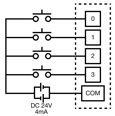
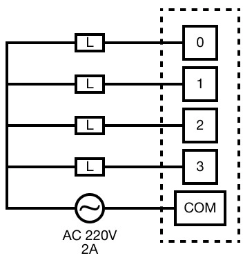
Circuit Diagrams
DC Input
Relay Output
Communication Channels
| Communication Channels | Description |
|---|---|
| USB | USB 2.0: Loader Protocol |
| Serial | RS-232(C) (115,200bps maximum) RS-485 (57,600bps maximum) MapleLogic Loader Modbus RTU Master & Slave User Protocol |
| Ethernet | 10/100 Base-T/TX MapleLogic Loader Modbus TCP Slave |
Utility Ports
| Utility Port | Description |
|---|---|
| Serial | RS-232 RS-422 RS-485 |
| Ethernet | RJ45 |
| USB | USB Mini-B |
| SD Card | – |
Maximum Expansion Modules
| Maximum Expansion Modules | 11 expansion modules + CPU 12 module chassis total |
Special Program
| Special Program | Description |
|---|---|
| High-Speed Counter | ✓ |
| Positioning | – |
| PID | ✓ |
Source Modular CPU Physical Specifications
| Specifications | PLC-ES1616P | PLC-ES0808P |
|---|---|---|
| Weight | 141g | 146g |
| Dimensions | 30mm x 64mm x 91mm 1.181in x 2.519in x 3.582in | 30mm x 64mm x 91mm 1.181in x 2.519in x 3.582in |
| Input Type | Universal (Sink/Source) | Universal (Sink/Source) |
| Digital Input Points | 16 | 8 |
| Rated Input Voltage | DC 12V-24V 0.58A 0.58A DC 12V is used for the High-Speed Counter | DC 12V-24V 0.58A 0.58A DC 12V is used for the High-Speed Counter |
| Rated Input Current | 4mA | 4mA |
| Input Insulation Method | Photocoupler | Photocoupler |
| Input Voltage/Current Threshold | ON: Channel 1 ~ 4: DC 10V/4mA Channel 5 ~ 8: DC 14V/4mA OFF: Channel 1 ~ 4: DC 6V/1mA Channel 5 ~ 8: DC 12V/1mA | ON: Channel 1 ~ 4: DC 10V/4mA Channel 5 ~ 8: DC 14V/4mA OFF: Channel 1 ~ 4: DC 6V/1mA Channel 5 ~ 8: DC 12V/1mA |
| Output Type | Source | Source |
| Digital Output Points | 16 | 8 |
| Rated Output Voltage | DC 12-24V | DC 12-24V |
| Rated Output Current | 1 Point: 0.2A COM: 2A | 1 Point: 0.2A COM: 2A |
| Output Insulation Method | Photocoupler | Photocoupler |
| Input Response Time | 3ms or less | 3ms or less |
| Output Response Time | 1ms or less | 1ms or less |
| Operation Indication | Input ON LED ON | Input ON LED ON |
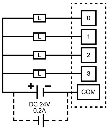
Circuit Diagram
DC Input
TR Output
Communication Channels
| Communication Channels | Description |
|---|---|
| USB | USB 2.0: Loader Protocol |
| Serial | RS-232(C) (115,200bps maximum) RS-485 (57,600bps maximum) MapleLogic Loader Modbus RTU Master & Slave User Protocol |
| Ethernet | 10/100 Base-T/TX MapleLogic Loader Modbus TCP Slave |
Utility Ports
| Utility Port | PLC-ES1616P | PLC-ES0808P |
|---|---|---|
| Serial | RS-232 RS-422 RS-485 | RS-232 RS-422 RS-485 |
| Ethernet | RJ45 | RJ45 |
| USB | USB Mini-B | USB Mini-B |
| SD Card | ✓ | – |
Maximum Expansion Modules
| Maximum Expansion Modules | 11 expansion modules + CPU 12 module chassis total |
Special Program
| Special Program | PLC-ES1616P | PLC-ES0808P |
|---|---|---|
| High-Speed Counter | ✓ | ✓ |
| Positioning | ✓ | ✓ |
| PID | ✓ | ✓ |
Modular CPU Performance Specification
| Specifications | All Modular CPUs |
|---|---|
| Program Control | Cyclic execution Time driven interrupt Stored Program |
| Input/Output Control | Indirect method Directed by program instruction |
| Program Languages | Instruction List (IL) Ladder Diagram (LD) Sequential Function Chart (SFC) Function Block Diagram (FBD) FBD Extension |
| Data Processing Method | 32-bit (4 Bytes) |
| Instructions (Sequence) | 60 |
| Instruction (Application) | 480 |
| Processing Speed (LD/MOV/Floating-point Arithmetic) | 300ns/step |
| Floating-point Arithmetic | Support for floating-point arithmetic |
| Number of Program Blocks | 128 Blocks Maximum |
| Operation Mode | Remote RUN Remote STOP |
| Data Preservation Against Power Failure | K data register Conservation (latch) in M, L, T, C, S, and D data registers |
Supporting Program
| Supporting Program | Description |
|---|---|
| Ladder Diagram (LD) | Scan Subroutine Initialize (COLD) Initialize (HOT) Periodic Interrupt |
| Special Configuration | Initializing Expansion Module PID Control I/O input module filter setting High-speed counter Positioning (relay output excluded) |
| Communication | User protocol (Serial & Ethernet) Modbus Master (RTU) Modbus Slave (RTU & TCP) High-speed Ethernet Link Security Web server |
| SFC (Sequential Function Chart) | SFC Program |
| FBD (Function Block Diagram) | FBD FBD Extension |
| Specifications | All Modular CPUs |
|---|---|
| Periodic Interruption | 15 Maximum Cycle setting (10ms ~ 60,000ms, Unit: 10ms) Priority setting (0~14) |
| Self-Diagnosis | Monitoring process delay Watch Dog Timer (Detects delay of scan time) Memory error I/O error Low battery power ON/OFF status |
| Watch Dog Timer (WDT) | 10ms ~ 5,000ms Unit: 10ms |
| Restarting | Cold Restart Hot Restart |
| Timer | Cycle: 0.01s ~ 6,553.5s (10ms or 100ms) On delay Addition Monostable Retriggerable TC (current value) TS (setting value) |
| Counter | Counter range: -32,768 ~ 32,767 Up counter Down counter Up or Down counter Ring counter CC (current value) CS (setting value) |
| Event Log | 16 log maximum (Power, Mode, Error) |
| PID | 32 channels (loops) Auto-tuning support |
| High-Speed Counter | 1 Phase: 20KHz 2 Phase: 10KHz |
| Positioning (Relay Output CPU Excluded) | X-axis: Position & Speed control 100,000pps Y-axis: Position control 5,000pps, Speed control 100,000pps |
| Features | I/O Reservation RTC Online-Edit Optional: SD/MMC Slot |
| Capacity of Scan Program | 10,000 Steps |
Data Registers Memory
| Data Register | Memory |
|---|---|
| X | 8 points (X0.0 ~ X0.7) |
| Y | 8 points (Y1.0 ~ Y0.7) 16 points (Y1.0 ~ Y0.F) |
| M | 8,192 points (M000.0 ~ M511.F) |
| L | 4,096 points (L000.0 ~ L255.F) |
| K | 4,096 points (K000.0 ~ K255.F) |
| F | 2,048 points (F000.0 ~ F127.F) |
| T | 512 points (T000 ~ T511) |
| C | 512 points (C000 ~ C511) |
| S | 100 × 100 steps (00.00 ~ 99.99) |
| D | 10,000 WORDs (D0000 ~ D9999) |
| Z | 1,024 WORDs Call Stack: Z00 ~ Z63, Z1000 ~ Z1063 |
| Q | 8,192 points (Q000.0 ~ Q511.F) |
| R | 16 WORDs (Index) |
Memory Allocation
All PLC-ES CPUs are allocated the first two works of X (X0.0 ~ X1.F) and first two WORDs of Y (Y0.0 ~ Y1.F)
Physcial Y outputs are accessed using Y1.0 ~ Y1.F.
Y0.0 ~ Y0.F are used internally and will NOT result in physical output.
Memory Allocation Example
- For example, if using the PLC-ES1616P, the CPU utilizes both X (input) and Y (output).
- Both allocations begin at WORD 0 (X0.0 and Y0.0)
- As shown on the No Card line, the next expansion module begins at 20, meaning X2.0 and Y2.0.
- As a result, the CPU utilizes X0.0 ~ X1.F and Y0.0 ~ Y1.F.