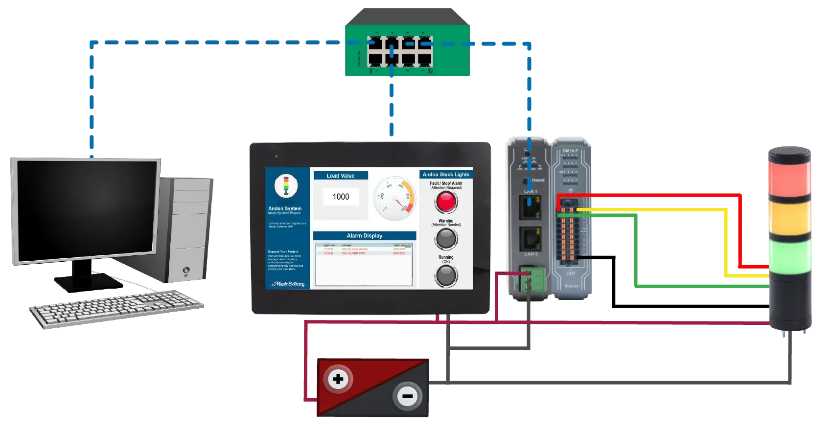
In a manufacturing facility, an operator uses a Maple Systems HMI to monitor machine status, cycle times, and fault conditions. When a problem occurs such as a machine fault, part jam, quality check failure, or material shortage, the HMI sends the event to the Andon system.

The Andon system then:
- turns on the appropriate stack light color
- triggers an audible alarm if required
- displays the fault location and reason on a central Andon board.
This allows supervisors, maintenance, and quality teams to immediately see where the problem is and what type of issue occurred, without walking the line or checking multiple machines.
By connecting the HMI to the Andon system, the HMI becomes the decision point for when an Andon call is generated, based on real machine data, alarms, and operator input.
This reduces response time, improves line visibility, and helps teams resolve issues faster to minimize downtime and production losses.
Software Required
Hardware Required
- Any Maple Systems HMI can be used. (cMT3108XP used in this example)
- Any Maple Systems Remote I/O Coupler can be used. (iR-ETN used in this example)
- Any Maple Systems Remote I/O Module can be used. (iR-DM16-P used in this example)
- Any Maple Systems Tower Stack Lights (TL1 Series) can be used.
Wiring and Network Configuration
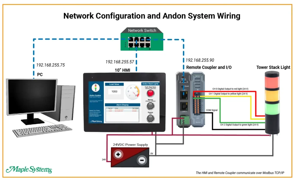
This diagram above shows a simple PLC-less Andon system where a PC, a 10-inch HMI, and a remote I/O station are all connected to the same Ethernet switch and assigned their own IP addresses (192.168.255.75 for the PC, 192.168.255.57 for the HMI, and 192.168.255.90 for the Remote coupler). The PC handles configuration and commissioning. The HMI communicates directly with the remote I/O over Ethernet to control the field devices. The remote I/O module sends 24‑volt digital output signals to the Andon light tower.
This setup allows the HMI to turn the red, yellow, and green indicator lights on and off based on operator commands or system conditions. It also removes the need for a PLC.
*Note – You only need the PC to initally download the project to the HMI.
A 24 VDC power supply feeds the remote I/O coupler on the left.
- +24 V goes to the coupler’s 24 V terminal.
- 0 V goes to the coupler’s 0 V terminal.
Coupler is connected to a DM16-P digital output module (the right-hand I/O module).
DM16-P is configured as a sourcing (PNP) output module (noted by “Source” at the bottom of the module).
Three digital output channels from the DM16-P are used to drive a 3-color stack light:
- CH 0 – Red light (24 V output)
- CH 1 – Yellow light (24 V output)
- CH 2 – Green light (24 V output)
The stack light has a common return (0 V).
All lamp segments share a single 0 V (ground) wire.
That black wire returns to the 0 V terminal on the output module.
Remote I/O Configuration
After downloading and installing EasyRemote I/O, open the software on your PC to begin configuring your Maple Systems remote I/O.
EasyRemote I/O Setup
Follow the steps below to set up your coupler and I/O using EasyRemote I/O.
Instructions: EasyRemote I/O Setup
Adding Network Coupler
Click the Add Network Coupler button in the toolbar.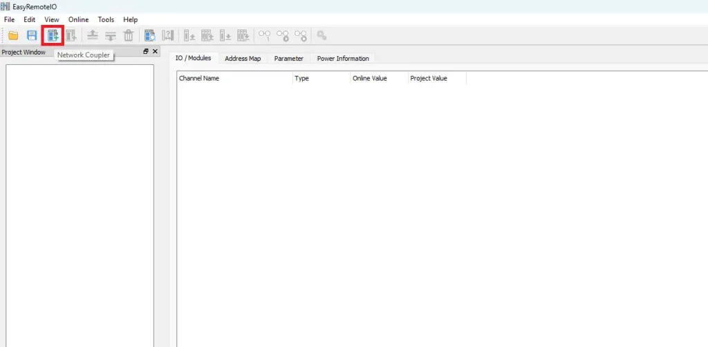
Selecting remote I/O coupler
Select the appropriate remote I/O coupler. In this example, the iR-ETN Ethernet coupler is used. Enter the coupler’s IP address. For this setup, the IP address is 192.168.255.15.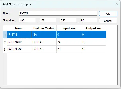
Add network coupler to the project
Once entered, the network coupler is added to the EasyRemote I/O project.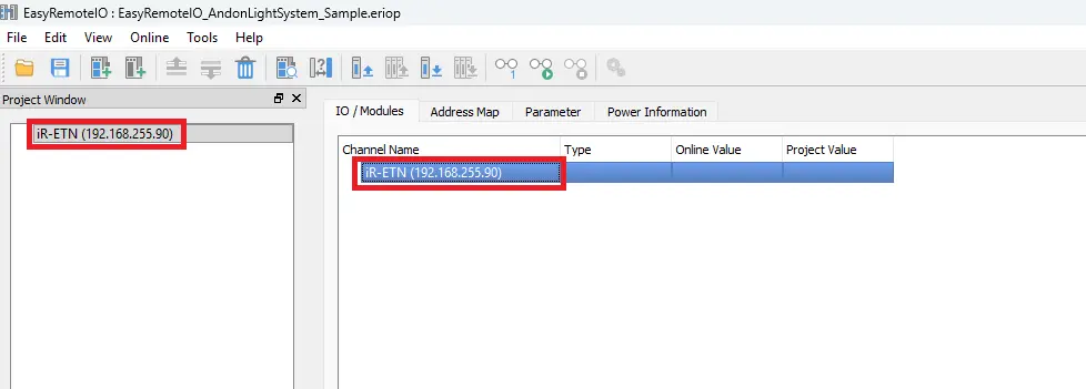
Adding I/O module
Click the Add Module button in the toolbar.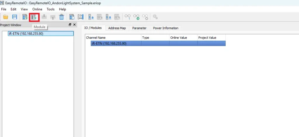
Select the I/O module type
Select the I/O module type. In this example, a DM16-P digital output module is used.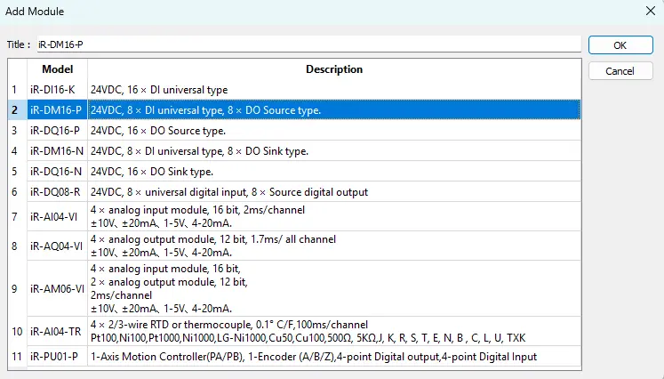
Add I/O module to the project
The digital I/O module is now added to the project and ready for configuration.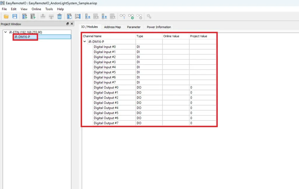
HMI Setup
After downloading and installing EBPro, open the software on your PC to begin setting up your Maple Systems HMI project.
EBPro Setup
We will set up the HMI using the EBPro software.
Instructions: EBPro Setup
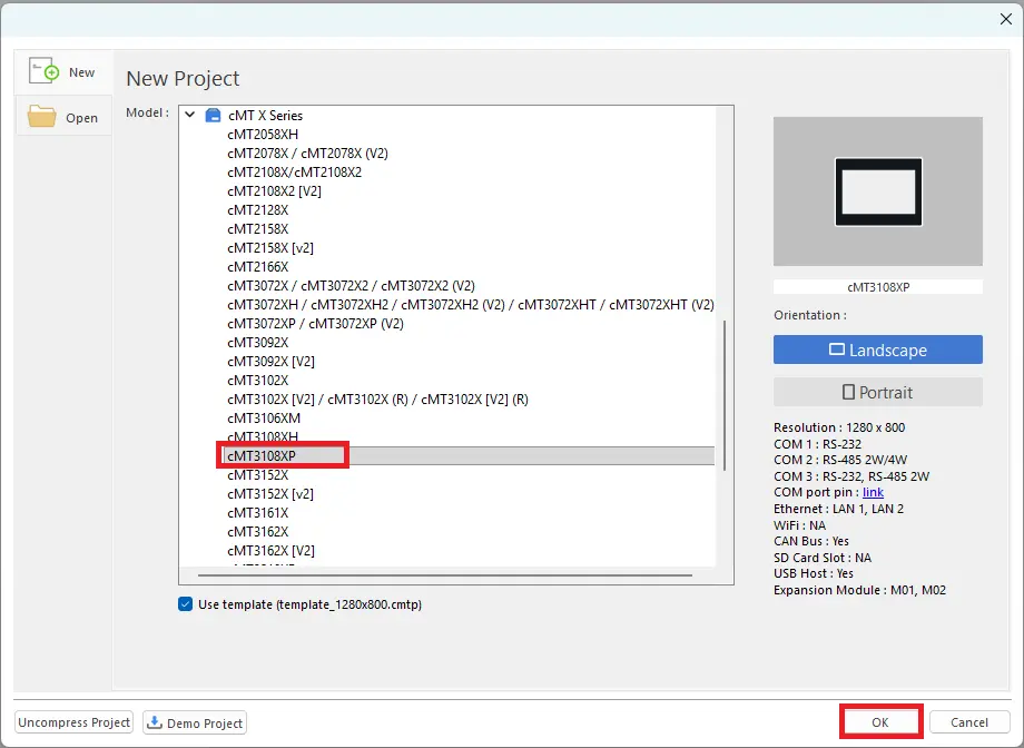
Create a new project
Start by adding a new project in EBPro.
For this example, select the cMT3108XP HMI model.
Add the Remote I/O Device
Click New Device/Server.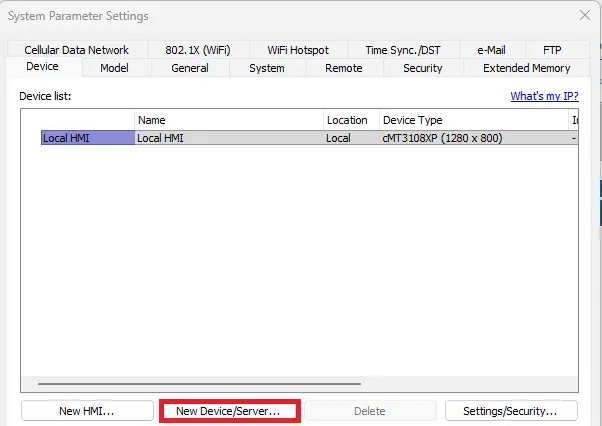
Select the device
Select Remote I/O (Modbus TCP/IP) as the device type.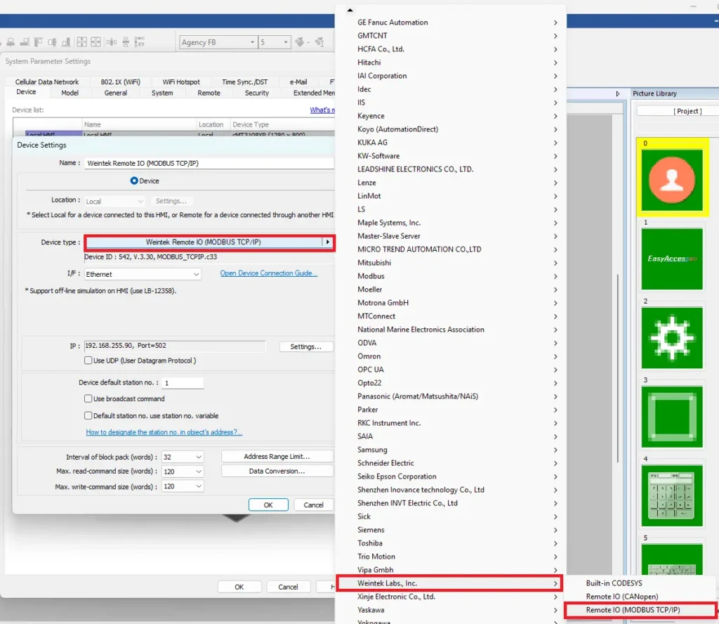
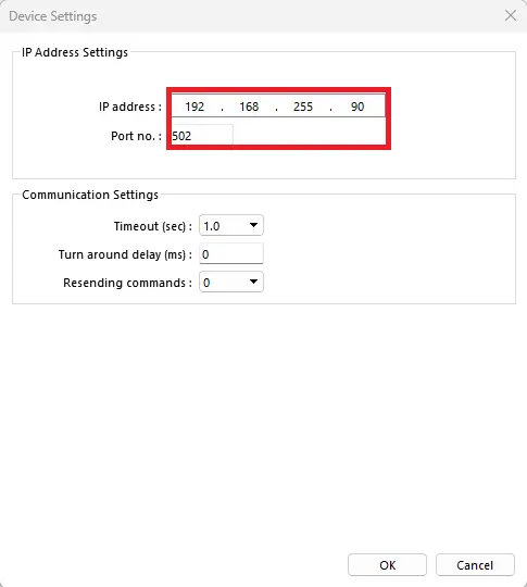
Device Settings
Open the device Settings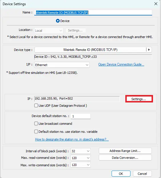
IP address
Ensure the IP address matches the Remote I/O module’s IP.
Enter the modbus port number : 502.
HMI Project Build
After configuring the EBPro settings, we can build the project.
EBPro Project
Now we will build the project.
Instructions: EBPro Project
Build the project (example of creating an Andon Light System project in EBPro)
Navigate to Object. Select the Bit Lamp button on the toolbar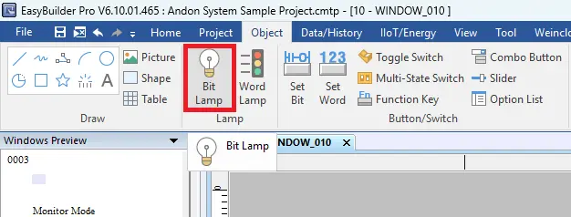
Add the Bit Lamps to the project
Place the Bit Lamps into the project and add textEdit the shapes and color states of the bit lamps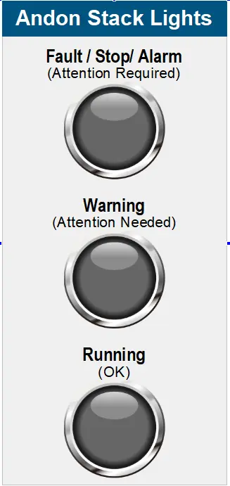
Add a numeric input object
Navigate to Object. Select the Numeric icon on the toolbarThis will represent the load amount. It will determine which indicator light turns on (bit lamps).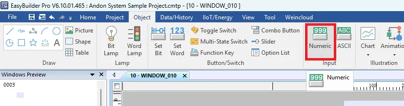
Add the numeric input object to the project
Place the numeric object into the project. Add text above the object.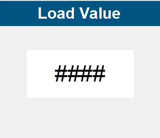
Add Event (Alarm) Log
Select the Event (Alarm) Log icon on the toolbar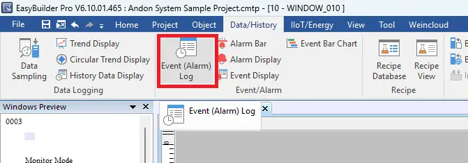
Add New Event (Alarm) Logs
Click New… to add a new Event (Alarm) Log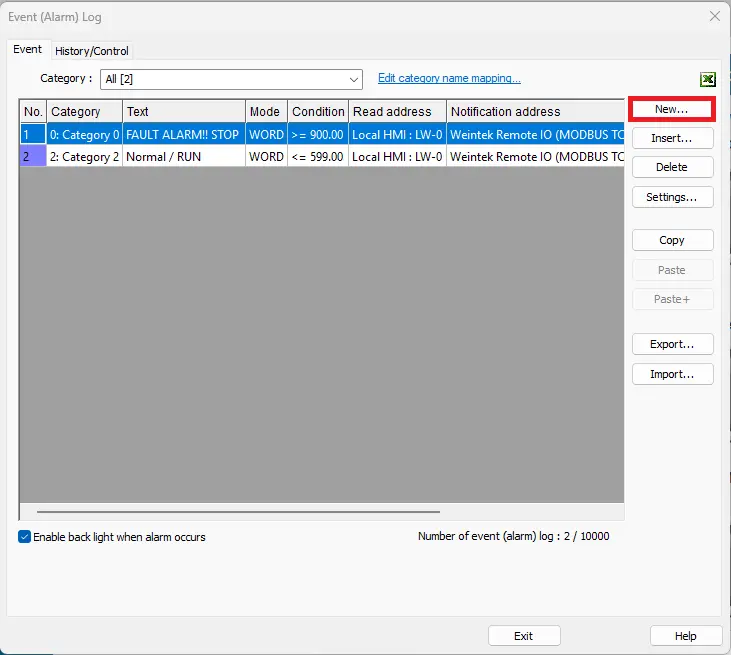
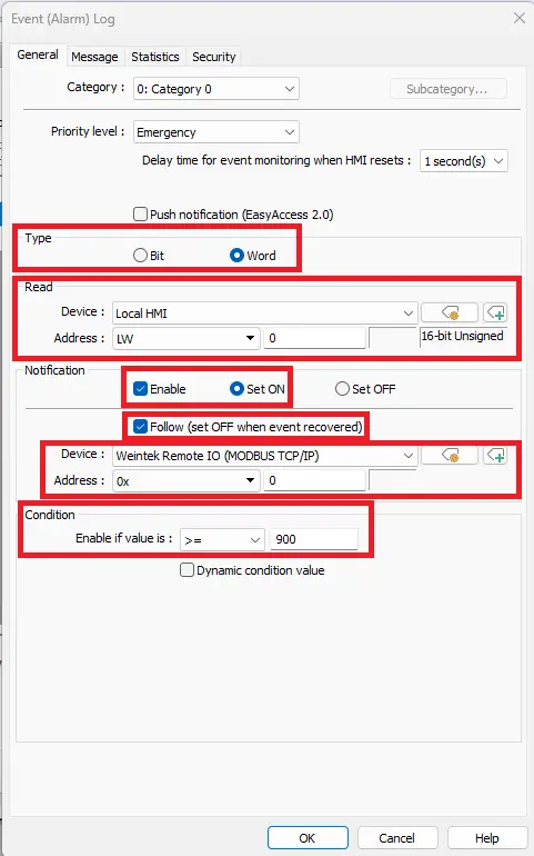
Edit Event (Alarm) Log
- For this example, change the Type to Word.
- The Read Device will be the Remote IO (MODBUS/TCP/IP)
Address is LW_0
- Notification set to Enable and Set ON – Need to enable this to receive an alarm message
- Check off Follow (set OFF when event recovered) – Bit Lamp will turn off when it’s out of the condition range
- Condition is set to Enable if value is >= 900 for the Fault Alarm.
Add Alarm Display
Navigate to Data/History. Select the Alarm Display button on the toolbar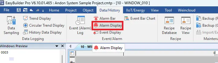
Add Alarm Display into the project
Place the Alarm Display into the project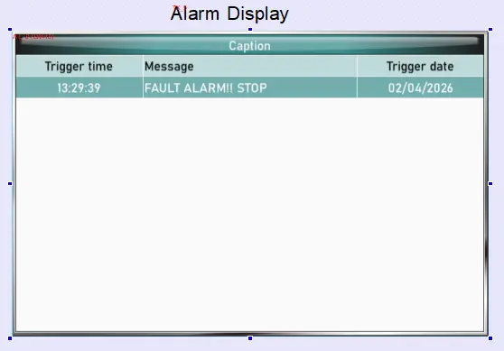
Edit the Alarm Display
Enable Acknowledge – when the alarm is acknowledged it will change color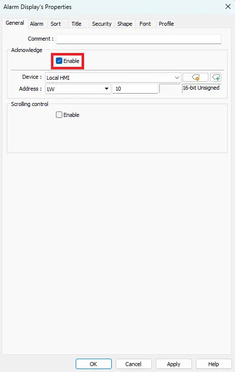
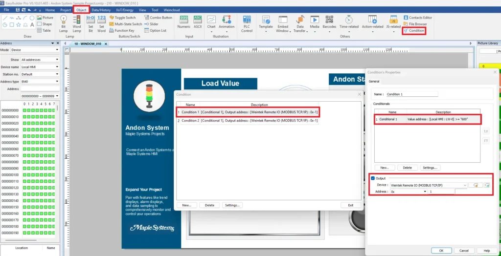
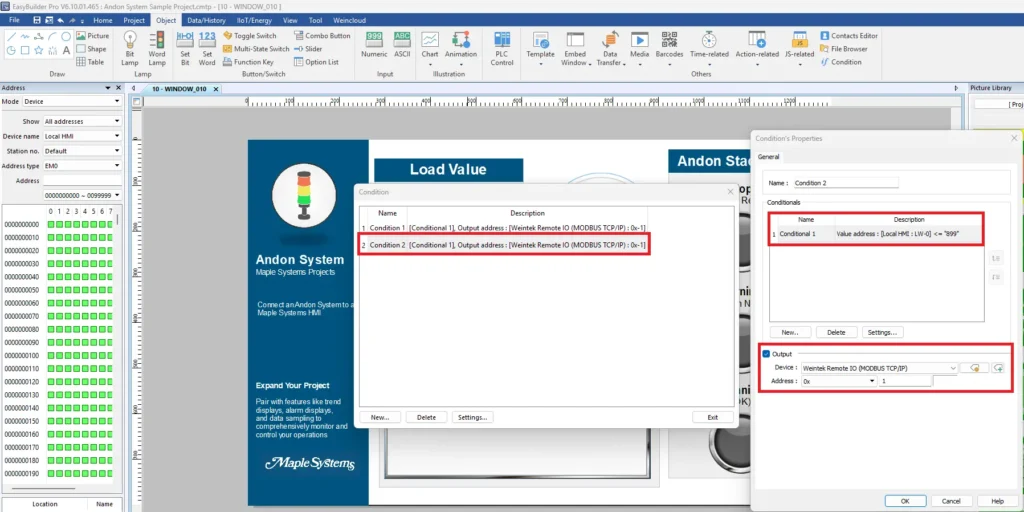
Adding a Condition Object for Warning Amber Light – 1st Condition
- Open your EBPro project.
- Select the Object tab from the ribbon.
- Click Condition.
- In the Condition window, click New.
- Enter a descriptive name for the condition (for example, Condition 1).
- Under Conditionals, click New or Settings to configure the condition.
- Select the value to monitor.
Device: Local HMI
Address: LW-0
- Configure the comparison.
Operator: >=
Value: 600
- Click OK to save the conditional expression.
- Enable the Output checkbox.
- Configure the output address.
Device: Remote IO (MODBUS TCP/IP)
Address Type: 0x
Address: 1
- Click OK to save the condition.
Adding a Condition Object for Warning Amber Light – 2nd Condition
- In the Condition window, click New to create another condition.
- Enter a descriptive name (for example, Condition 2).
- Under Conditionals, configure the comparison.
Device: Local HMI
Address: LW-0
Operator: <=
Value: 899
- Enable the Output checkbox if it is not already selected.
- Configure the same output address.
Device: Remote IO (MODBUS TCP/IP)
Address Type: 0x
Address: 1
- Click OK to save the condition.
Live Simulation
The following simulation demonstrates how the system responds to different load values. Based on the configured thresholds, the HMI updates the alarm display and activates the corresponding Andon stack light status.
Normal Operation (0–599)
When the load value remains within the normal operating range, the system continues running without interruption. Thus, no alarms are triggered, and the green stack light remains active to indicate normal operation.
Warning Condition (600–899)
When the load approaches the upper operating limit, the system enters a warning state. The machine enters the warning state, and according to the “if” condition the HMI activates the amber stack light to indicate that attention may soon be required.
Fault / Stop Alarm (950)
When the load reaches the critical threshold, the system triggers a fault condition. As a result, the machine stops immediately, the HMI records the event, and the red stack light activates to indicate an alarm state.
Modbus Ethernet Communication
Configure the modbus addressing in EasyRemote IO and EBPro.
Modbus Addressing
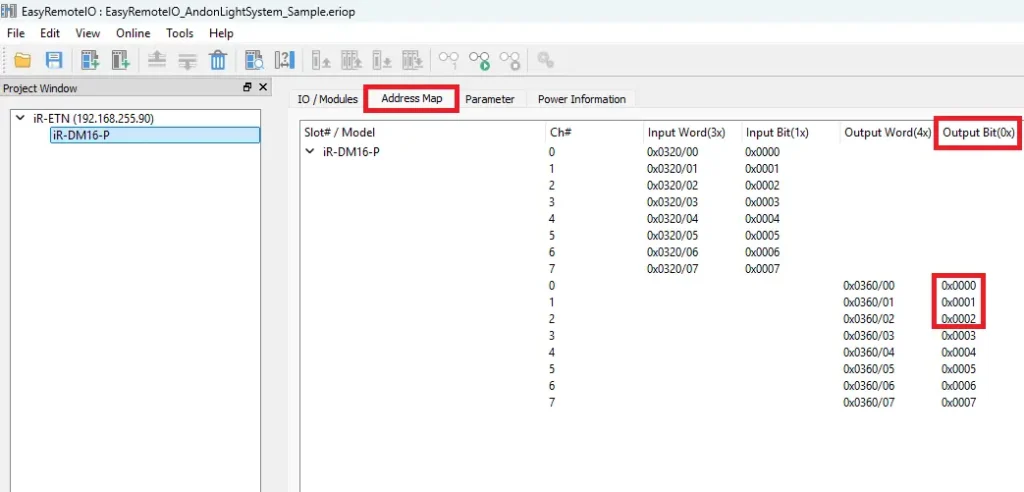
Back in EasyRemote I/O, the next step is to review the address map, which is essential for communicating with your Maple Systems HMI via Modbus TCP. In this example, we will have three digital outputs representing the signal to the Andon light stack.
Instructions: Modbus Addressing
In EasyRemote I/O select the channel
- Channels 0,1, and 2 will be our outputs on the DM16-P
- The modbus addresses are 0x, 0x_1, 0x_2
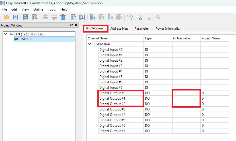
Monitor the Digital Output in EasyRemote I/O
- Navigate to the I/O / Modules tab.
- The channel value will display 0 when off and 1 when on, providing real-time feedback of the digital output state.
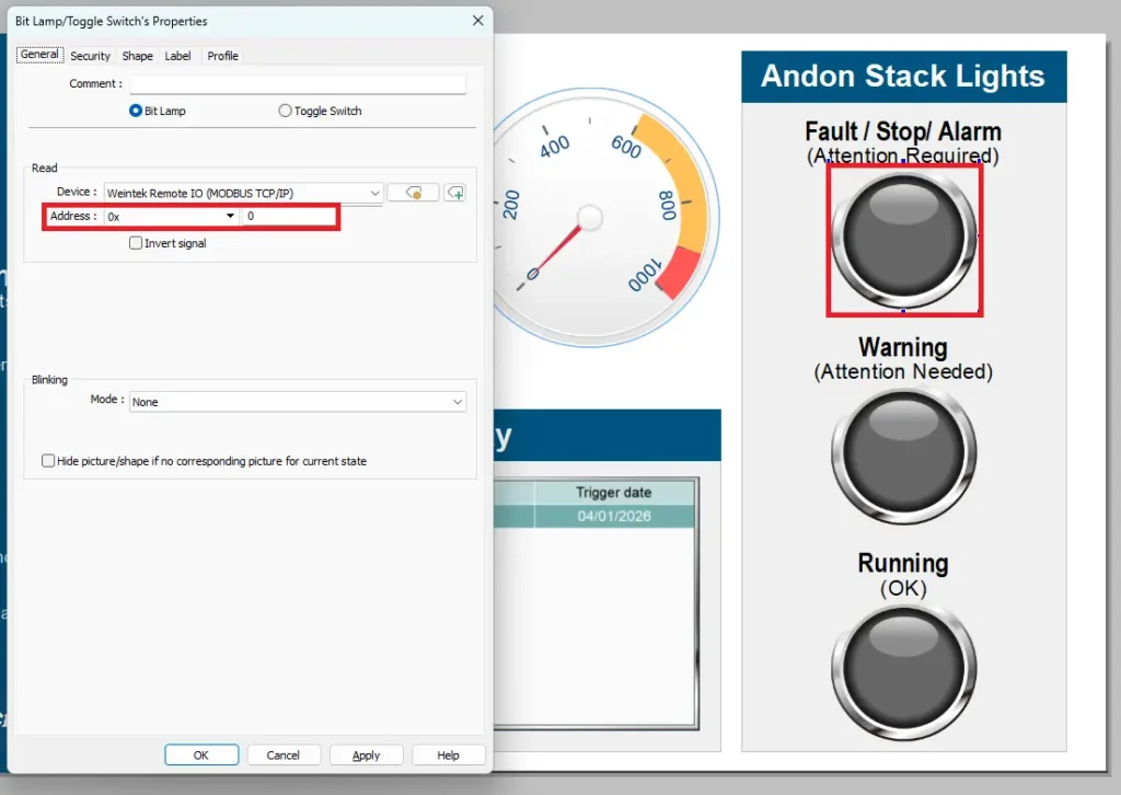
Configure Modbus Addressing in EBPro
- In your EBPro project, double-click the bit lamp objects.
- Assign it to the Remote I/O device and set the Modbus address to 0x_0 to match Ch# 0 on the iR-DM16-P.
- Assign the other bit lamps to their corresponding modbus address so they match in EBPro and in EasyRemote I/O. The other two would be 0x_1 and 0x_2.
Recap
To summarize what we learned. In this system, the HMI acts as the decision and control point by monitoring conditions and determining when an Andon event should occur. The HMI communicates with the remote I/O over Modbus TCP to send output commands. The remote I/O converts those commands into physical digital output signals. These signals drive the stack light, turning the red, yellow, and green indicators on and off to show machine status.
Next Steps
A practical next step is to verify communication by monitoring the output channels in EasyRemote I/O while toggling the HMI indicators in EBPro. Once basic operation is confirmed, add real machine conditions, alarms, or operator inputs in the HMI project to automatically trigger the correct Andon color. Finally, test and document the fault, warning, and running scenarios to validate the system before putting it into production.
Sample Projects
This integration tutorial uses the EasyRemote IO and EBPro Sample Projects.
Resources & Documentation
The following guides and documentation are specific to the hardware used in this integration tutorial and will help you with setup, configuration, and programming:
- EasyRemote IO
- EasyRemote IO User Guide
- Remote I/O Datasheet
- EBPro
- EBPro Programming Manual
- TL1 Quick Start Guide
- TL160D2F-1 Datasheet
- TL160P2F-1 Datasheet
Looking for additional learning resources? Explore our library of tutorials, example projects, and software tools to help you get the most out of your system:
Also, browse our Support Center for a complete list of installation guides, FAQs, and additional technical documentation.

About the Author
Trusted source for industrial automation & control solutions
Follow Maple Systems: