
Instruction Parameters
Supported PLC Series
| PLC-AES | PLC-FB | PLC-ES |
|---|---|---|
| ✓ | ✓ | ✓ |
Supported Data Registers
| M | X | Y | K | L | F | T | C | S | Z | R | Q | D | @D | Constant | |
|---|---|---|---|---|---|---|---|---|---|---|---|---|---|---|---|
| S | ✓ | ✓ | ✓ | ✓ | ✓ | – | – | – | – | ✓ | – | ✓ | ✓ | ✓ | ✓ |
| D | ✓ | – | ✓ | ✓ | ✓ | – | – | – | – | ✓ | ✓ | ✓ | ✓ | ✓ | – |
| n | ✓ | ✓ | ✓ | ✓ | ✓ | ✓ | ✓ | ✓ | – | ✓ | ✓ | ✓ | ✓ | ✓ | ✓ |
Supported Flags
| Flag | Bit | Support |
|---|---|---|
| Error | F11.0 | ✓ |
| Zero | F11.1 | – |
| Carry | F11.2 | – |
Number of Steps
| Steps |
|---|
| 4 |
Operands
| Operand | Description |
|---|---|
| S | The first operand. Entries are only encoded WORD data registers. This is the value to be decoded. |
| D | The second operand. Entries are only WORD data registers. This is where the decoded data is saved. 2 × n data registers may be required. |
| n | The third operand. Entries are WORD data registers or constants. This is the exponent of 2n for the amount of bits to be decoded. The value range is 1 ~ 8. |
Notice
Error Flag (F11.0) Notice
The error flag, F11.0, will be ON for one scan when the address of the data register assigned by @D exceeds the range of the data register, D. The range of the data register, D, is dependent on the CPU type. F11.0 turns ON when the value of the data for n is not in range of 1 ~ 8.
Instruction Behavior
The DECO and DECOP instructions behave as follows:
- The absolute value of n bits is read and stored in the data register S. The corresponding bit starting from the WORD data register D is turned ON while all other bits are turned OFF.
- A maximum of 8 bits are decoded.
- This results in 256 bits (16 WORDs) total.
- Decoding starts from the least significant bit of the data register, S.
- According to the absolute value of the specified bits, the corresponding bit starting from the data register D is turned ON.
- 2n bits of the data register D are preoccupied when the instruction executes.
Ladder Diagram Examples
DECO

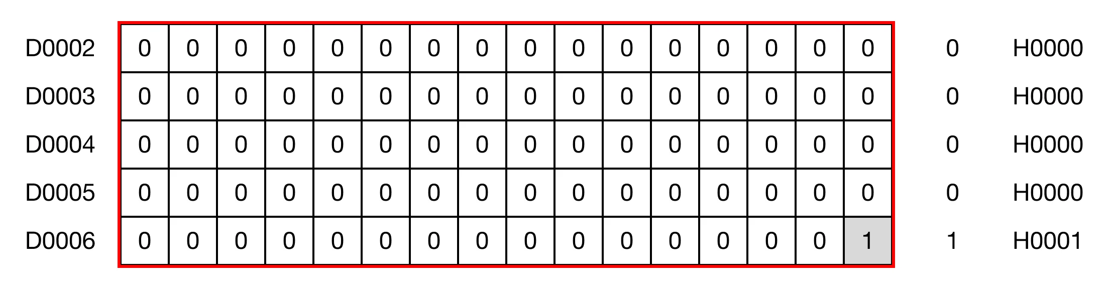
The DECO instruction decodes the absolute value of n bits saved in the data register S and turns the corresponding bits ON starting from the data register D. All other bits in the data register D are turned OFF.

When the contact, M0.0 is ON (1), the instruction decodes 27 bits of the data register, D0, and stores the result in D2.

Memory Monitor

DECOP

The DECOP one-shot instruction decodes the absolute value of n bits saved in the data register S and turns the corresponding bits ON starting from the data register D. All other bits in the data register D are turned OFF. Every time this instruction executes, it energizes the output only once.

When the contact, M0.1 is ON (1), the instruction decodes 25 bits of the data register, D10, and stores the result in D12.

Memory Monitor

