
Instruction Parameters
Supported PLC Series
| PLC-AES | PLC-FB | PLC-ES |
|---|---|---|
| ✓ | ✓ | ✓ |
Supported Data Registers
| M | X | Y | K | L | F | T | C | S | Z | R | Q | D | @D | Constant | |
|---|---|---|---|---|---|---|---|---|---|---|---|---|---|---|---|
| DEV | ✓ | ✓ | ✓ | ✓ | ✓ | ✓ | ✓ | ✓ | – | ✓ | ✓ | ✓ | ✓ | ✓ | ✓ |
| TBL | – | – | – | – | – | – | – | – | – | ✓ | ✓ | ✓ | ✓ | ✓ | – |
Supported Flags
| Flag | Bit | Support |
|---|---|---|
| Error | F11.0 | ✓ |
| Zero | F11.1 | – |
| Carry | F11.2 | – |
Number of Steps
| Steps |
|---|
| 3 |
Operands
| Operand | Description |
|---|---|
| DEV | The first operand. Entries are WORD data registers or constants. This is the value to write to the table. The signed value range is -32,768 ~ 32,767 (216). The unsigned value range is 0 ~ 65,535 (216-1). The Hexadecimal value range is H0000 ~ HFFFF. |
| TBL | The second operand. Entries are only WORD data registers. This is the starting address for the table. |
Notice
Error Flag (F11.0) Notice
The error flag, F11.0, will be ON for one scan when the address of the data register assigned by @D exceeds the range of the data register, D. The range of the data register, D, is dependent on the CPU type. F11.0 turns ON when the data table exceeds the range of the corresponding data register.
Instruction Behavior
The FIFW and FIFWP instructions behave as follows:
- If there is already data saved to TBL, DEV will be saved to the next available slot of TBL.
- The overall amount of data saved in TBL will increase by 1.
- The first value of TBL is an integer number representing the amount of data saved in TBL.
Execution Condition
The FIFW instruction must be used with a pulse contact or an open contact with the FIFWP instruction due to the instruction continuously executing. If the execution goes past the last possible data register block number, an error occurs and F11.0 turns ON.
Ladder Diagram Examples
FIFW

The FIFW instruction writes the WORD value from the data register, DEV, into the table, TBL, starting at an offset of 1 (TBL + 1).


When the contact, M1.0, is powered ON (1), the FIFW instruction writes 1 to the data register, D2.

As a result, 90 is written to the data register, D3 (D2 + 1).

When the FIFW instruction is executed again, the data register, D2, increases its count by one to 2.

As a result, -853 is written to the data register, D4 (D2 + 2).

When the FIFW instruction is executed again, the data register, D2, increases its count by one to 3.
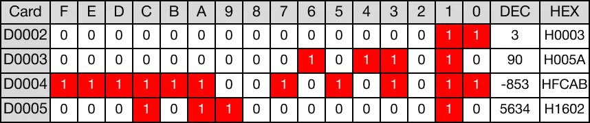
As a result, 5,634 is written to the data register, D5 (D2 + 3).

When the FIFW instruction is executed again, the data register, D2, increases its count by one to 4.
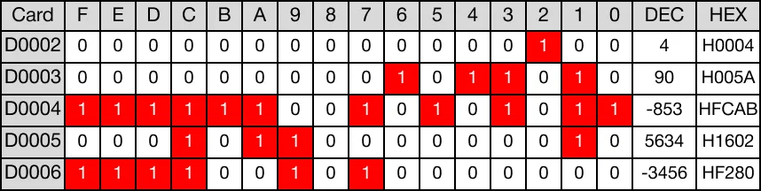
As a result, -3,456 is written to the data register, D6 (D2 + 4).
FIFWP

The FIFWP one-shot instruction writes the WORD value from the data register, DEV, into the table, TBL, starting at an offset of 1 (TBL + 1). Every time this instruction executes, it energizes the output only once.


When the contact, M1.1, is powered ON (1), the FIFWP instruction writes 1 to the data register, D7.

As a result, 32,124 is written to the data register, D8 (D7 + 1).

When the FIFWP instruction is executed again, the data register, D7, increases its count by one to 2.

As a result, -9,645 is written to the data register, D9 (D7 + 2).

When the FIFWP instruction is executed again, the data register, D7, increases its count by one to 3.
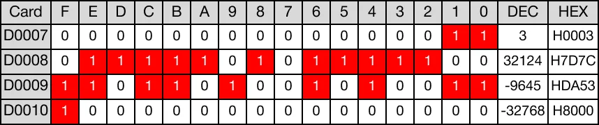
As a result, -32,768 is written to the data register, D10 (D7 + 3).