
Modbus RTU Master Communication Program
Modbus RTU is a widely-used communication protocol in industrial automation systems, designed for transmitting data over Serial connections. It follows the client-server architecture where the Modbus Master (client) initiates communication by sending requests to connected devices, known as Modbus Slaves (servers). The Master controls the serial connection, querying the Slaves for data or commanding actions. Each Slave responds to the Master’s request, providing data such as sensor readings, device status, or executing commands. Modbus RTU ensures reliable, real-time data exchange in various automation applications, enhancing system interoperability and efficiency.
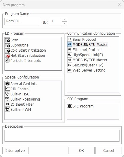
This example will cover the Modbus RTU Master Communication program.
Requirements and Assumptions:
- This example will use two Maple Systems PLCs.
- PLC-FB1616R0202 (slave)
- PLC-ES0808P (master)
- Both PLCs are on the same network with the same subnet mask and gateway.
- The PLCs are directly connected to each other using a 5-pin serial cable.
Slave PLC
The following will occur on the PLC-FB1616R0202, which is the slave PLC.
Step 1: Create a new project
Register Scan Program
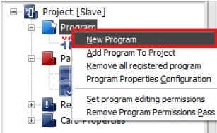
Step 2: Create a new scan program by right-clicking Program and left-clicking New Program.
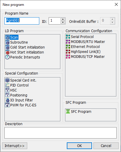
Step 3: Left-click Scan and left-click OK to continue.
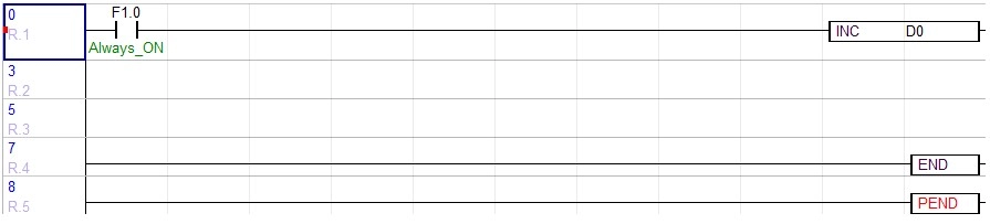
Step 4: Add the instruction to the scan program:
- Normally open contact with the Always ON internal flag, F1.0.
- This will execute the instruction, INC D0.
- For more information about the instruction, refer to the INC instruction.
- For every scan, 1 will be added to the data register D0.
- This will execute the instruction, INC D0.
Download Changes to the Slave
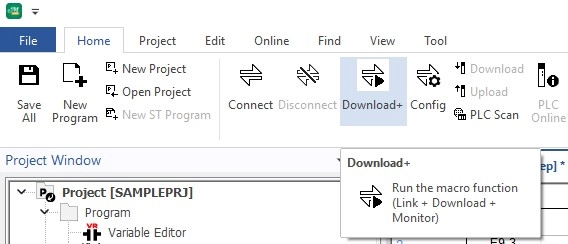
Step 5: Left-click the Download icon.
- Optionally, left-click Online and left-click Link+Download+Monitor.
This is all that is needed for the slave PLC.
Master PLC
The following will occur on the PLC-ES0808P PLC, which is the master.
Step 6: Create a new project. This will be separate from the slave PLC project.
Register Modbus RTU Master Special Program
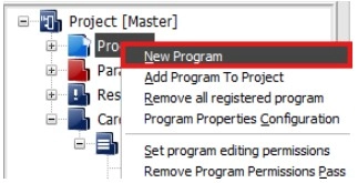
Step 7: Create a new Modbus RTU Master special program by right-clicking Program and left-clicking New Program.
Step 8: Left-click MODBUS/RTU Master and left-click OK when finished.
Configure Modbus RTU Master Special Program
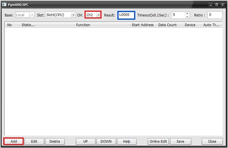
Step 9: In the Program Window, change the CH (channel number) to Ch2 for channel 2. This will use RS-422/RS-485 for communication. The result will utilize the L data registers starting at L0.
Step 10: Left-click Add.
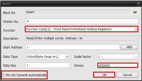
Step 11: Make the following changes and left-click OK when finished:
- Change the Function to Function Code[3].
- Change the Device to D0000.
- Toggle Do not transmit automatically.
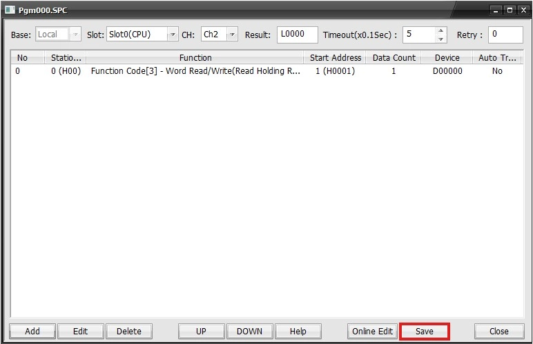
Step 12: Left-click Save.
Register Scan Program
Step 13: Create a new scan program by right-clicking Program and left-clicking New Program.
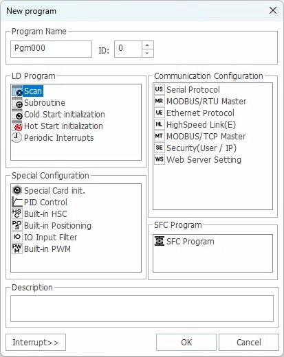
Step 14: Left-click Scan and left-click OK to continue.
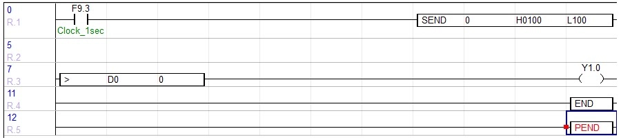
Step 15: Add the following instruction to the scan program:
- Positive Transition-Sensing Contact with a 1-second clock internal flag, F9.3.
- This will execute the instruction, SEND 0 H0100 L100.
- 0 is the program ID for the Modbus RTU special program.
- H0100 is the frame to send on channel 2.
- L100 is a data register for any communication data from Modbus.
- For more information about the instruction, refer to the SEND instruction.
- This will execute the instruction, SEND 0 H0100 L100.
Step 16: Add the following additional instruction to the scan program:
- Add the instruction > D0 0.
- This will energize the coil, Y1.0, every time D0 is greater than 0.
- For more information about the instruction, refer to the greater than (>) instruction.
- D0 is the data register being used in the slave program.
- It is now accessible via Modbus in the master program.
- This will energize the coil, Y1.0, every time D0 is greater than 0.
Download Changes to the Master

Step 17: Left-click the Link+Download+Monitor icon.
- Optionally, left-click Online and left-click Link+Download+Monitor.
This is all that is needed for the master PLC.
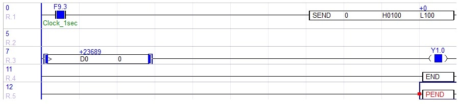
- The value of D0 will change, meaning the value is being read from the slave PLC.
- When the coil, Y1.0, is OFF, D0 is less than 0.