
Ladder Logic
MapleLogic offers ladder diagram language for making PLC projects. Ladder logic is entered in Scan programs.
Basic Ladder Diagram Composition
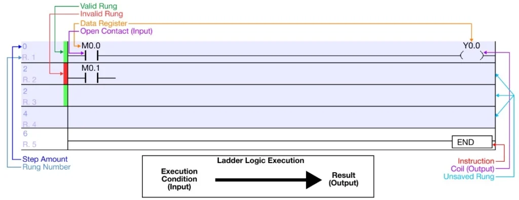
- Standard ladder diagram Scan programs will look like the diagram above
- Step Amount:
- Each contact, coil, instruction, etc., cost a certain amount of steps.
- The step number for the rung is listed on the far left of the rung (highlighted in dark blue).
- Invalid Rung:
- Incomplete rungs or invalid rungs that are added to the program, but not saved, will show a red vertical line on the far left of the rung.
- This rung is incomplete since there is no resulting condition attached to the normally open contact M0.1 (highlighted in red).
- Rung Number:
- Each new and separate rung will display the rung number with the notation R.# on the far left of the rung (highlighted in gray).
- Valid Rung:
- New and complete rungs will show a green vertical line on the far left of the rung (highlighted in green).
- Unsaved Rungs:
- Any rung that has been added to a Scan program, or any rung that has a change made to it and has not been saved, will appear highlighted.
- In this example, the top 3 rungs are highlighted in light blue.
- Any rung that has been added to a Scan program, or any rung that has a change made to it and has not been saved, will appear highlighted.
- Instructions:
- Instructions added to the Scan program will typically have a black box around them while listing the instruction name and operands, if any (highlighted in red).
- Execution Condition (Input) → Result Instruction (Output):
- Typically, in ladder logic, execution occurs from left to right.
- An execution, input button for example, triggers, and the resulting output, light for example, energizes (light lights up).
- Step Amount:
Add Rungs
Step 1: add more rungs to the ladder diagram, left-click the rung where new rungs will be added. New rungs will be added above the selected rung.
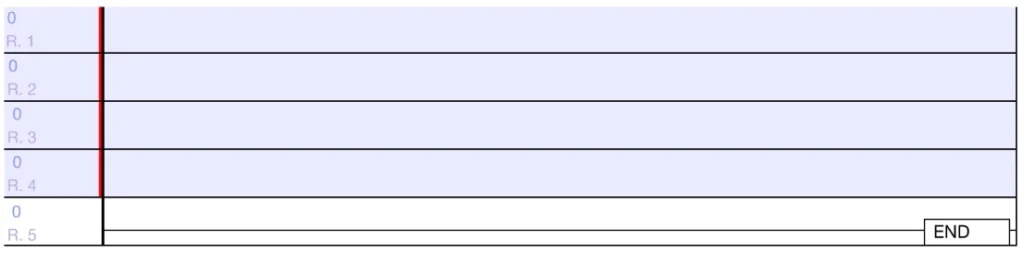
Step 2: Press CTRL + L to insert a new rung.
- If changes have been made to the ladder diagram, the changed rung will appear as a different color.
- Additionally the program title will have an asterisk, *, next to the name.
- This means the program has NOT been saved since recent changes were made.
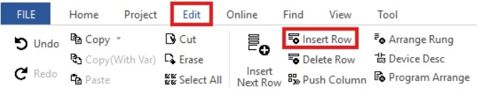
- Alternatively, to insert a new rung, left-click Edit and left-click Insert Row.
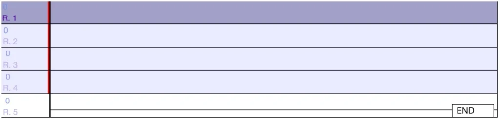
Step 3: To insert a rung below the currently selected rung, left-click the rung and press CTRL + Enter.
- The new rung will be inserted below the selected rung.
- Alternatively, to insert a rung below the selected one, left-click Edit and left-click Insert Next Row.
Columns
Enable/Disable Columns
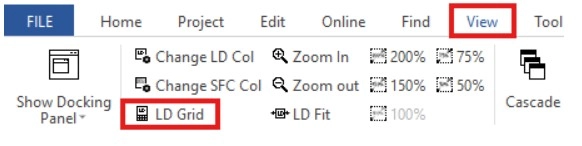
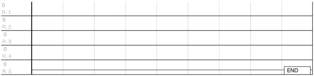
Step 1: Columns can be added to the ladder logic program. To enable or disable column view, left-click View and left-click LD Grid to toggle columns on or off.
Change Column Size
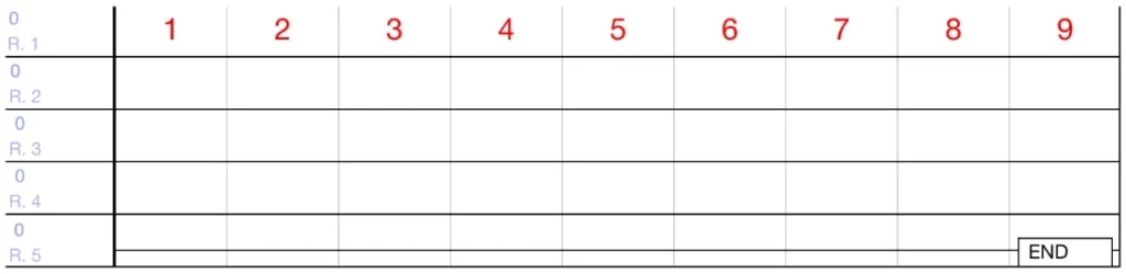
- The amount of columns per rung can be increased or decreased.
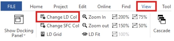
Step 1: To change the amount of columns, left-click View left-click Change LD Col.
Step 2: Specify the number of columns to display per rung.
- Minimum: 9
- Maximum: 80
- Default: 11
Step 3: Left-click OK.
- The number of columns will change.
Toolbar and Tools

Step 1: To use the ladder logic toolbar, left-click View.

- The ladder diagram toolbar has 14 different components:
- Arrow
- Erase Vertical Line
- Delete Vertical Line
- Horizontal Line
- Invert
- Normally Open Contact
- Normally Closed Contact
- Positive Transition-Sensing Contact
- Negative Transition-Sensing Contact
- Coil
- Application Instruction
- Comment
- Function Block
Arrow

- The arrow tool will restore the mouse cursor if it is being occupied by another MapleLogic component
Erase
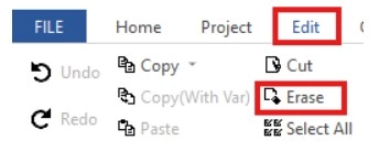
- The erase tool will delete the components of the ladder diagram.
Erase Tool
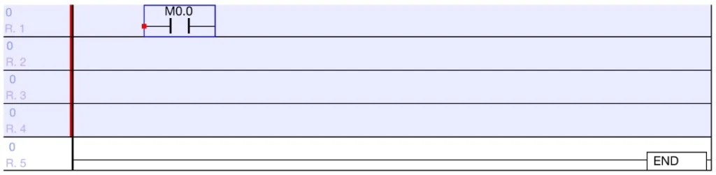
Step 1: Left-click on the component to delete
Step 2: On the tool bar, left-click Erase
- Optionally, use the DELETE key on the keyboard
- The erased component will be deleted
Vertical Line

- The vertical line tool will create a vertical line between rungs.
Vertical Line Tool
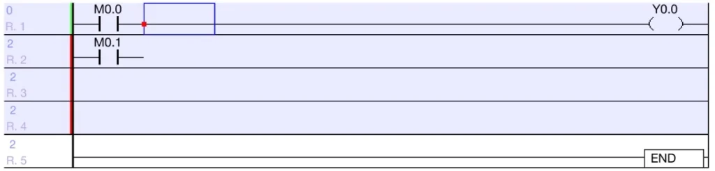
Step 1: Left-click the rung to add the top of the vertical line.
- This will connect the currently selected rung with the below rung.
Step 2: On the toolbar, left-click the Vertical Line icon.
- Optionally, type SHIFT + F2 or CTRL + DOWN ARROW.
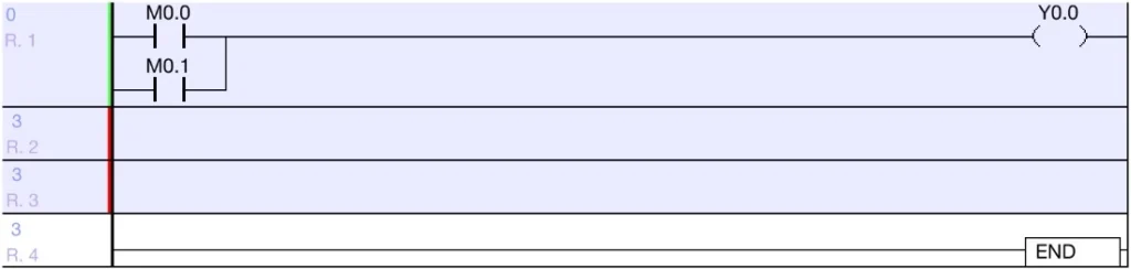
- A vertical line will be placed in front of the open contacts.
- The lower of the rungs is no longer invalid.
- This creates a basic OR gate connection.
Delete Vertical Line

- The delete vertical line tool will remove a vertical line connecting two rungs.
Delete Vertical Line Tool
Step 1: Left-click the space next to the component to delete the connecting vertical line.
Step 2: On the toolbar, type CTRL + F2 or left-click below rung and type CTRL + UP ARROW.
- The two rungs will no longer be connected.
Horizontal Line

- The horizontal line tool will create a horizontal line in the same rung.
Horizontal Line Tool
Step 1: Left-click a space in the ladder diagram.
Step 2: On the toolbar, left-click the Horizontal Line icon.
- Optionally, type F2, CTRL + LEFT ARROW or CTRL + RIGHT ARROW.
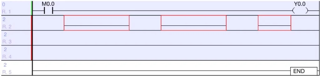
- Individual horizontal lines will be added into the ladder diagram.
Invert

- The inversion tool will insert an inversion component to invert the signal from an execution condition.
- If the signal from the execution condition is OFF (0), the resulting output will energize/be ON (1).
- If the signal from the execution condition is ON (1), the resulting output will deenergize/be OFF (0).
Invert Tool
Step 1: Left-click the space to place the inversion.
Step 2: On the toolbar, left-click Invert.
- Optionally, type F4.
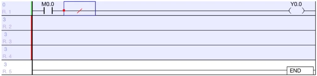
- The inversion signal will show a red slash through the middle of a horizontal line.
Normally Open Contact

- The normally open contact tool will place a normally open contact in the ladder diagram.
- While ON (1), normally open contacts receive a continuous source of power and execute the resulting operation until powered OFF (0).
- The resulting operation will be executed many times per scan.
- While ON (1), normally open contacts receive a continuous source of power and execute the resulting operation until powered OFF (0).
Normally Open Contact Tool
Step 1: Left-click the rung to insert a new normally open contact.
Step 2: On the toolbar, left-click Contact A.
- Optionally, type F5.
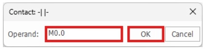
Step 3: Enter the data register and left-click OK.
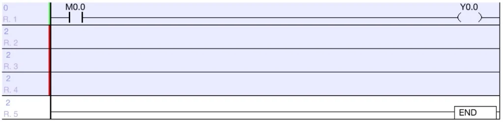
- The open contact will be added to the rung.
- Multiple normally open contacts can be added to a rung.
- The creates a basic AND Gate connection.
Normally Closed Contact

- The normally closed contact tool will place a normally closed contact in the ladder diagram.
- While OFF (0), normally closed contacts output a continuous source of power and execute the resulting operation until powered ON (1).
- The resulting operation will be executed many times per scan.
- For more information, refer to closed contacts.
- While OFF (0), normally closed contacts output a continuous source of power and execute the resulting operation until powered ON (1).
Normally Closed Contact Tool
Step 1: Left-click the rung to insert a new normally closed contact.
Step 2: On the toolbar, left-click Contact B.
- Optionally, type F6.
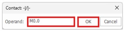
Step 3: Enter the data register and left-click OK.
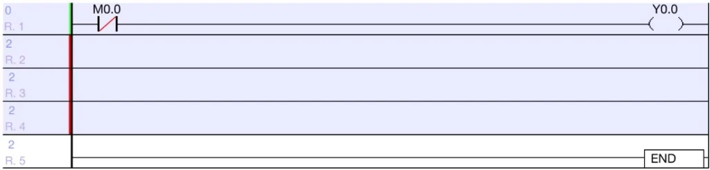
- The closed contact will be added to the rung.
- Multiple normally closed contacts can be added to a rung.
- Thos creates a basic AND Gate connection.
Positive Transition-Sensing Contact

- The positive transition-sensing contact tool will place a positive transition-sensing contact in the ladder diagram.
- The resulting operation will be executed once each time the contact receives power.
- The execution condition is executed on the rising edge of a pulse
- For more information, refer to rising edge contacts.
Positive Transition-Sensing Contact Tool
Step 1: Left-click the rung to insert a new positive transition-sensing contact.
Step 2: On the toolbar, left-click Pulse Up.
- Optionally, type F7.
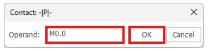
Step 3: Enter the data register and left-click OK.
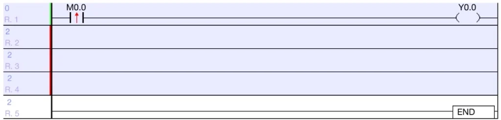
- The positive transition-sensing contact will be added to the rung.
- Multiple positive transition-sensing contacts can be added to a rung.
- This creates a basic AND Gate connection.
Negative Transition-Sensing Contact

- The negative transition-sensing contact tool will place a negative transition-sensing contact in the ladder diagram.
- The resulting operation will be executed once each time the contact receives power.
- The execution condition is executed on the falling edge of a pulse.
- For more information, refer to falling edge contacts.
Negative Transition-Sensing Contact Tool
Step 1: Left-click the rung to insert a new negative transition-sensing contact.
Step 2: On the toolbar, left-click Pulse Down.
- Optionally, type F8.
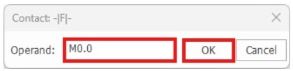
Step 3: Enter the data register and left-click OK.
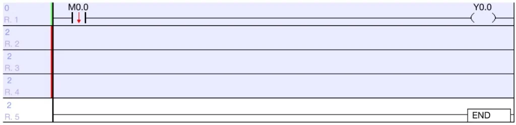
- The negative transition-sensing contact will be added to the rung.
- Multiple negative transition-sensing contacts can be added to a rung.
- This creates a basic AND Gate connection.
Coil

- The coil tool will create a coil at the end of a rung.
Coil Tool
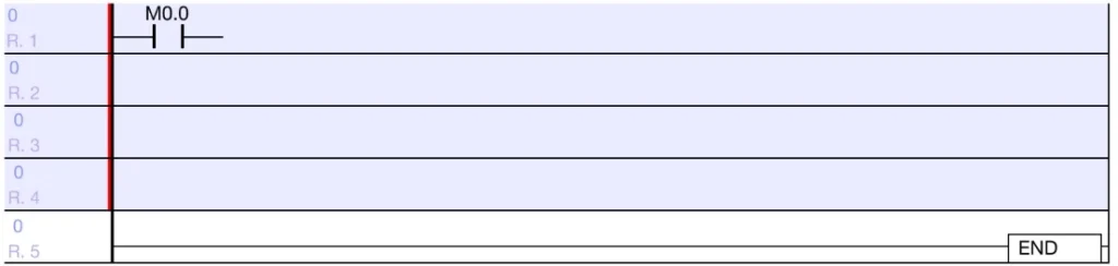
Step 1: Left-click on any space in the rung.
Step 2: On the toolbar, left-click Coil.
- Optionally, type F9.
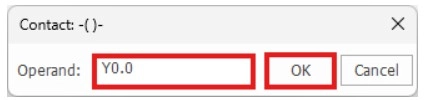
Step 3: Enter the data register and left-click OK.
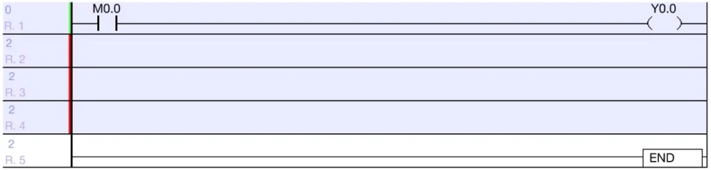
- The coil will be placed at the end of the rung.
- Only one coil can be placed per rung.
- It is advised to have one occurrence of each coil per scan program.
Application Instruction

- The application instruction tool will insert an application instruction into the ladder diagram.
- Most application instructions will execute a command/instruction when the execution condition is true.
- Refer to the Application Instruction section for more information.
Application Instruction Tool
Step 1: Left-click on any space in the rung.
Step 2: On the toolbar, left-click Application Instruction.
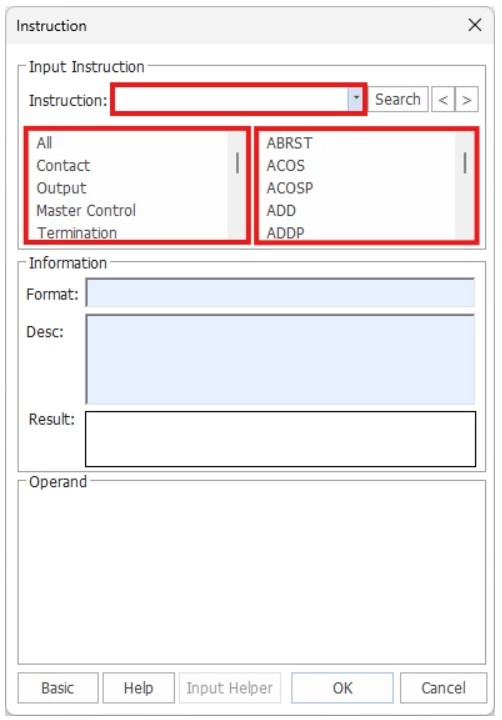
- Optionally, type F10, or type any character on the keyboard
- The application instruction window will appear.
Step 3: Type the name of the instruction in the Instruction tab, or select the instruction category on the left and instruction on the right.
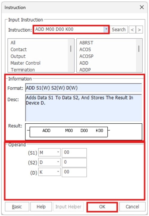
- The isntruction format will appear in the Instruction tab.
Step 4: Select the data registers required for the instruction.
Step 5: Left-click OK.
- Optionally, left-click Basic for a basic view of the instruction list.
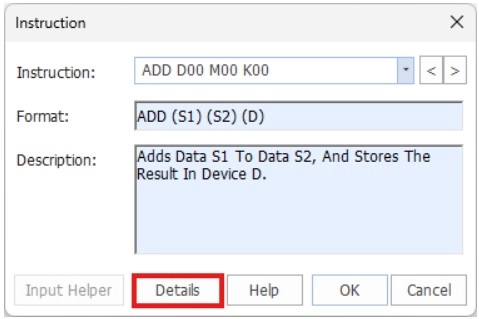
- Left-click Details to return to the previous view.
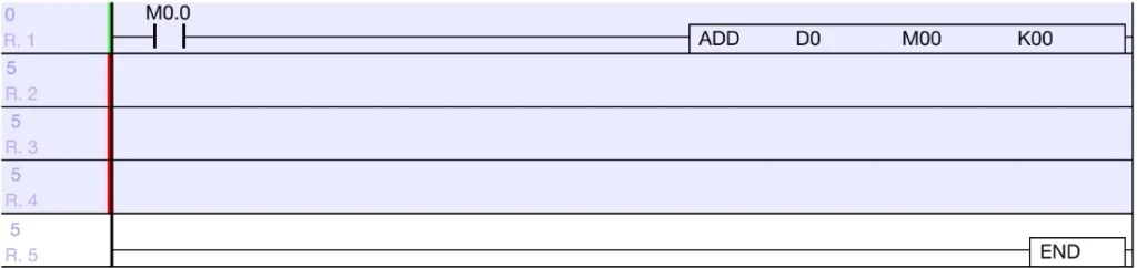
- The instruction will appear after the execution condition.
Comment

- The comment tool will insert a comment into the ladder diagram for organizational use.
Comment Tool
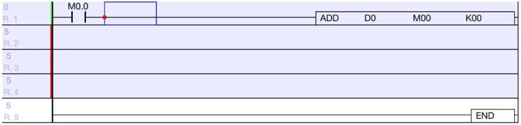
Step 1: Left-click on any space in the rung.
- The comment will be placed above the currently selected rung.
Step 2: On the toolbar, left-click the Comment icon.
- Optionally, type F12.
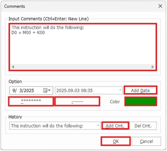
Step 3: Enter the comment into the Input Comments window.
- To enter a new line, type CTRL + ENTER.
- To add a date to the comment, left-click Add Date.
- To add a row of asterisks (*), left-click *******.
- To add a row of dashes (-), left-click ——–.
- To change the color of the comment, left-click Color.
- To add the comment as a historical comment to use elsewhere, left-click Add Cmt.
Step 4: Left-click OK.
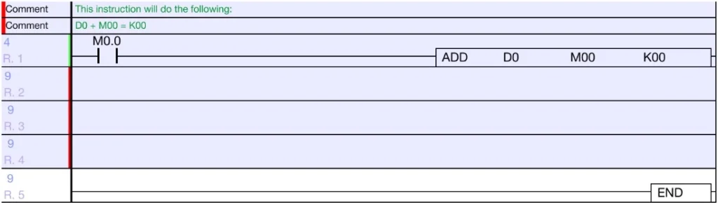
- The comment will appear above the rung.
Add Function Block

- The add function block tool will insert a function block into the ladder diagram.
Add Function Block Tool
Step 1: Left-click on any space on the rung.
Step 2: On the toolbar, left-click Add FB.
- Optionally, type SHIFT + F9.
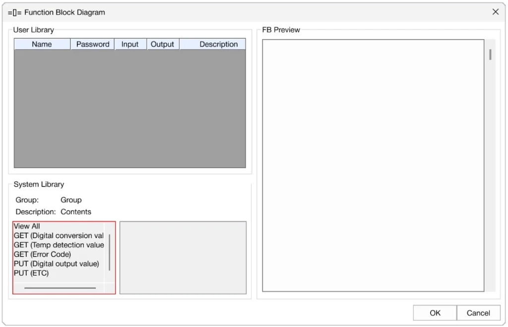
Step 3: Left-click a function block group.
Step 4: Left-click a function block.
- The function block requirements will appear in the FB Preview window.
Step 5: Left-click OK.
- The function block will appear in the ladder diagram.
Step 6: Double left-click on the function block to edit the data registers.
Step 7: Enter the data registers under the Device tab.
Step 8: Left-click OK.
- The function block will now display the data registers.
Save Program
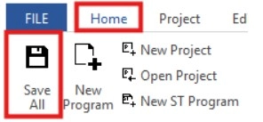
Step 1: To save the program, left-click Home and left-click Save All.
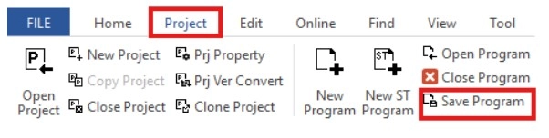
- Optionally, left-click Project and left-click Save Program.