
Digital-to-Analog (DA)
Navigate to Online → Special Module Setup → DA Module or click on the DA module within the Card Properties.
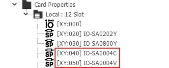
Applied Modules
- IO-SA0004C
- IO-SA0004V
DA Module Details
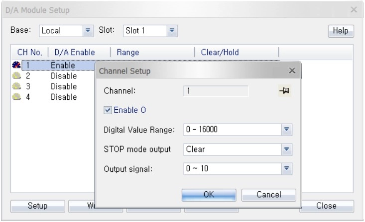
Step 1: Hold CTRL to configure all channels at once.
Step 2: Click Setup to enable/disable the module, or configure the digital value range, STOP mode output, or output signal.
Digital Value Range:
- 0 ~ 16,000
- -8,000 ~ 8,000
- 0 ~ 10,000 (percentage)
STOP Mode Output:
- Clear: If the CPU mode is set to STOP, the last value will be output.
- Hold: If the CPU mode is set to STOP, 0 will be output.
Output Signal:
- 0 ~ 10
- -10 ~ 10 (IO-SA0004V only)
Step 3: Once the settings are configured, click OK to confirm and apply the changes.
Step 4: To save the configured parameters to the PLC, click Write.
Step 5: Click Read to check the parameters.
Step 6: For real-time monitoring and module diagnostics, click Status. This displays the current value, minimum and maximum values, firmware version of the module, and any error codes.