Instruction Parameters
Supported PLC Series
| PLC-AES | PLC-FB | PLC-ES |
|---|---|---|
| ✓ | ✓ | ✓ |
Supported Data Registers
| M | X | Y | K | L | F | T | C | S | Z | R | Q | D | @D | Constant | |
|---|---|---|---|---|---|---|---|---|---|---|---|---|---|---|---|
| S1 | ✓ | – | ✓ | ✓ | ✓ | – | – | – | – | – | – | – | ✓ | ✓ | ✓ |
| S2 | ✓ | – | ✓ | ✓ | ✓ | – | – | – | – | – | – | – | ✓ | ✓ | ✓ |
| D1 | ✓ | – | ✓ | ✓ | ✓ | – | – | – | – | – | – | – | ✓ | ✓ | – |
| S3 | ✓ | – | ✓ | ✓ | ✓ | – | – | – | – | – | – | – | ✓ | ✓ | ✓ |
| D2 | ✓ | – | ✓ | ✓ | ✓ | – | – | – | – | – | – | ✓ | ✓ | ✓ | – |
Supported Flags
| Flag | Bit | Support |
|---|---|---|
| Error | F11.0 | ✓ |
| Zero | F11.1 | – |
| Carry | F11.2 | – |
Number of Steps
| Steps |
|---|
| 6 |
Operands
| Operand | Description |
|---|---|
| S1 | The first operand. Entries are WORD data registers or constants. This is the starting value. The signed value range is -32,768 ~ 32,767 (216). The unsigned value range is 0 ~ 65,535 (216-1). The Hexadecimal value range is H0000 ~ HFFFF. |
| S2 | The second operand. Entries are WORD data registers or constants. This is the final value. The signed value range is -32,768 ~ 32,767 (216). The unsigned value range is 0 ~ 65,535 (216-1). The Hexadecimal value range is H0000 ~ HFFFF. |
| D1 | The third operand. Entries are DWORD data registers. This is the current value of S1 changing to S2>. This requires 2 data registers. |
| S3 | The fourth operand. Entries are WORD data registers. This is the amount of scans it should take to change S1 to S2. The signed value range is -32,768 ~ 32,767 (216). The unsigned value range is 0 ~ 65,535 (216-1). The Hexadecimal value range is H0000 ~ HFFFF. |
| D2 | The fifth operand. Entries are BOOL data registers. This is the completion status of the change from S1 to S2. This requires 2 data registers. |
Notice
Error Flag (F11.0) Notice
The error flag, F11.0, will be ON for one scan when the address of the data register assigned by @D exceeds the range of the data register, D. The range of the data register, D, is dependent on the CPU type. F11.0 turns ON for one scan if the current value D1 does NOT reach the final value S2 even if the actual execution time has exceeded the S3 value.
Instruction Behavior
The RAMP instruction behaves as follows:
- When the current value, D1, reaches the final value, S2, the status BOOL data register, D2, turns ON.
- If the data register D2+1 is ON, the current value, D1, does NOT change in the following scans.
- If the data register D2+1 is OFF, the current value, D1, and status, D2, are initialized in the next scan, and the RAMP instruction executes again.
- The smallest possible value for the scan amount data register, S3, is 1.
- The largest possible value for the scan amount data register, S3, is 32,767.
- If the scan amount, S3, is 0, the RAMP instruction will not execute.
- The changed value per scan is calculated:
- Changed value per scan = (S2 – S1)/S3
Ladder Diagram Examples
RAMP

The RAMP instruction gradually changes the initial WORD value, S1, to the final WORD value, S2, in the number of scans, S3. The current value, D1, is saved as a DWORD data register where the data register, D1+1, is the current number of executions. The BOOL data register, D2, is the status of the gradual change of the initial WORD value, S1, to the final WORD value, S2, after completion.

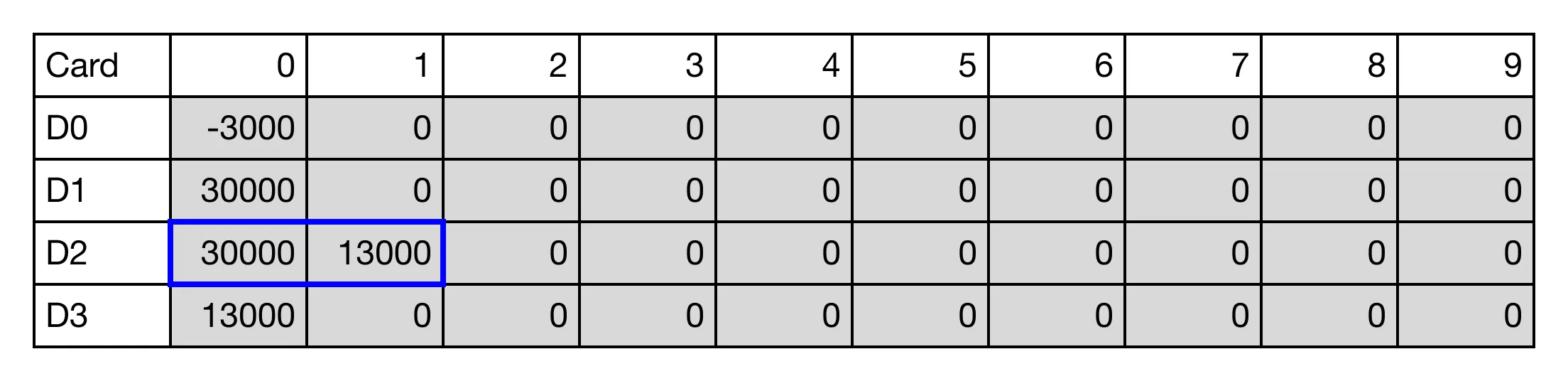
When the contact, M1.0 is ON (1), the initial value, -3,000, will gradually change to the final value, 30,000, in 13,000 scans. While gradually changing the value, the result bit, M0.0, is OFF.

The initial value, D0, is currently 5,768 (D20) at the current scan.

The initial value, D0, has gradually changed to 30,000 (D20) after 13,000 scans.

Once the change is complete, the result bit, M0.0, is ON.

Memory Monitor