Instruction Parameters
Supported PLC Series
| PLC-AES | PLC-FB | PLC-ES |
|---|---|---|
| ✓ | ✓ | ✓ |
Supported Data Registers
| M | X | Y | K | L | F | T | C | S | Z | R | Q | D | @D | Constant | |
|---|---|---|---|---|---|---|---|---|---|---|---|---|---|---|---|
| S | ✓ | ✓ | ✓ | ✓ | ✓ | ✓ | ✓ | ✓ | – | ✓ | ✓ | ✓ | ✓ | ✓ | ✓ |
| D | ✓ | – | ✓ | ✓ | ✓ | – | ✓ | ✓ | – | ✓ | ✓ | ✓ | ✓ | ✓ | – |
Supported Flags
| Flag | Bit | Support |
|---|---|---|
| Error | F11.0 | ✓ |
| Zero | F11.1 | – |
| Carry | F11.2 | – |
Number of Steps
| Steps |
|---|
| 3 |
Operands
| Operand | Description |
|---|---|
| S | The first operand. Entries are 8-digit binary coded decimal (BCD) data registers or constants. This is the value to be converted to ASCII code. The value range is H00000000 ~ H99999999 (BCD). |
| D | The second operand. Entries are only ASCII DWORD data registers. This is where the conversion is saved. The result will require 2 DWORD data registers. |
Notice
Error Flag (F11.0) Notice
The error flag, F11.0, will be ON for one scan when the address of the data register assigned by @D exceeds the range of the data register, D. The range of the data register, D, is dependent on the CPU type. F11.0 turns ON when the value of the data for processing exceeds the data register assigned to D.
Instruction Behavior
The DBCDDA and DBCDDAP instructions behave as follows:
- The ones digit of the conversion result is stored in the upper BYTE of the data register D+3.
- H20 is stored in the destination data register for the leading zeros of valid digits.
Ladder Diagram Examples
DBCDDA

The DBCDDA instruction converts an 8-digit binary coded decimal (BCD) value, S, into ASCII code. The conversion result is saved in 2 assigned DWORD data registers starting at the data register, D.

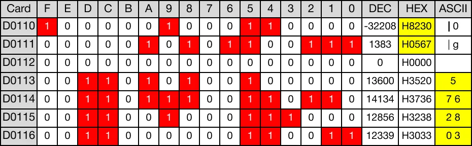
When the contact, M5.0, is powered ON (1), the DBCDDA instruction converts the value of the two BCD data registers, D110 and D111, into ASCII code.

The result of the conversion is saved in four ASCII data registers, D113, D114, D115, and D116.
Memory Monitor
DBCDDAP

The BCDDAP one-shot instruction converts an 8-digit binary coded decimal (BCD) value, S, into ASCII code. The conversion result is saved in 2 assigned DWORD data registers starting at the data register, D. Every time this instruction executes, it energizes the output only once.

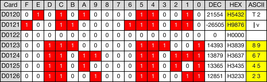
When the contact, M5.5, is powered ON (1), the DBCDDAP instruction converts the value of the two BCD data registers, D120 and D121, into ASCII code.

The result of the conversion is saved in four ASCII data registers, D123, D124, D125, and D126.
Memory Monitor