Instruction Parameters
Supported PLC Series
| PLC-AES | PLC-FB | PLC-ES |
|---|---|---|
| ✓ | ✓ | ✓ |
Supported Data Registers
| M | X | Y | K | L | F | T | C | S | Z | R | Q | D | @D | Constant | |
|---|---|---|---|---|---|---|---|---|---|---|---|---|---|---|---|
| D | ✓ | – | ✓ | ✓ | ✓ | – | ✓ | ✓ | – | ✓ | ✓ | ✓ | ✓ | ✓ | – |
| n | ✓ | ✓ | ✓ | ✓ | ✓ | ✓ | ✓ | ✓ | – | ✓ | ✓ | ✓ | ✓ | ✓ | ✓ |
Supported Flags
| Flag | Bit | Support |
|---|---|---|
| Error | F11.0 | ✓ |
| Zero | F11.1 | – |
| Carry | F11.2 | ✓ |
Number of Steps
| Steps |
|---|
| 3 |
Operands
| Operand | Description |
|---|---|
| D | The first operand. Entries are only WORD data registers. This is the value to shift to the left. The result of the shift will be saved here. The signed value range is -32,768 ~ 32,767 (216). The unsigned value range is 0 ~ 65,535 (216-1). The Hexadecimal value range is H0000 ~ HFFFF. |
| n | The second operand. Entries are WORD data registers or constants. This is the number of bits to shift. The value range is 0 ~ 15. The remainder n ÷ 16 will be the result of n if the value of n is greater than 15. |
Notice
Error Flag (F11.0) Notice
The error flag, F11.0, will be ON for one scan when the address of the data register assigned by @D exceeds the range of the data register, D. The range of the data register, D, is dependent on the CPU type. F11.0 turns ON when the value of the data for a shift exceeds the data register assigned to D.
Carry Flag (F11.2) Notice
The carry flag, F11.2, will be ON for one scan when the operation result overflows.
Instruction Behavior
The SFL and SFLP instructions behave as follows:
- IMG images/01-sfl-notice.webp – The value in the data register, D, is shifted to the left. Notice
- The value in the data register, D, is shifted to the left.
- The value is shifted in the direction of the most significant bit.
- The carry flag turns ON when 1 is shifted into the carry flag, F11.2.
- n should be a value from 0 ~ 15.
- If n is greater than 15, the remainder from n ÷ 16 is the equivalent.
- Example: if n = 18, the remainder is 2.
- This is the same as n = 2.
- Example: if n = 18, the remainder is 2.
- If n is greater than 15, the remainder from n ÷ 16 is the equivalent.
- Starting from the most significant bit, n bits are equal to 0.
- This occurs when the instruction is energized.
- Data from bit 0 ~ n-2 are lost after the instruction executes.
T and C Registers
With the T and C data registers, only the value of TC and CC can be shifted.
Execution Condition
It is recommended that the SFL instructions be used with a pulse contact as an execution condition, or use the SFLP instruction.
Ladder Diagram Examples
SFL

The SFL instruction will shift the WORD value, D, n number of bits to the left. The result of the rotation is saved in the same assigned WORD data register, D. The carry flag, F11.2, can be used.

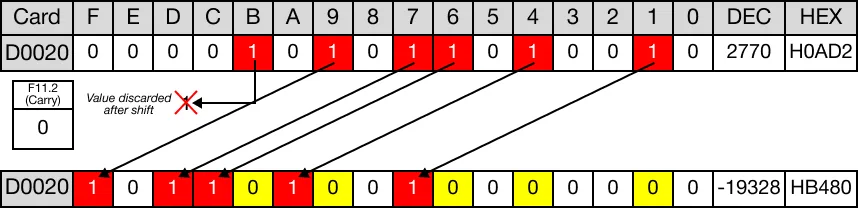
The initial value of the WORD data register, D20, is 2,770.

When the contact, M1.5, is powered ON (1), the instruction shifts the WORD data register, D20, 6 bits to the left.

The value of the WORD data register, D20, changes from 2,770 to -19,328.

The bit shifted past bit F is discarded.
When the instruction is reenergized, the WORD data register, D20, is shifted 6 bits to the left again.

The value of the WORD data register, D20, changes from -19,328 to 8,192.

The bits shifted past bit F are discarded.
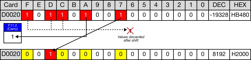
The last bit is shifted into the carry flag bit, F11.2.
SFLP

The SFLP one-shot instruction will shift the WORD value, D, n number of bits to the left. The result of the rotation is saved in the same assigned WORD data register, D The carry flag, F11.2, can be used. Every time this instruction executes, it energizes the output only once.

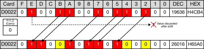
The initial value of the WORD data register, D22, is 19,636.

When the contact, M1.7, is powered ON (1), the instruction shifts the WORD data register, D22, 3 bits to the left.

The value of the WORD data register, D22, changes from 19,636 to 26,016.

The bit shifted past bit F is discarded.
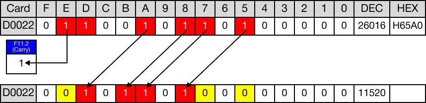
When the instruction is reenergized, the WORD data register, D22, is shifted 3 bits to the left again.

The value of the WORD data register, D22, changes from 26,016 to 11,520.

The last bit is shifted into the carry flag bit, F11.2.