
Instruction Parameters
Supported PLC Series
| PLC-AES | PLC-FB | PLC-ES |
|---|---|---|
| ✓ | ✓ | ✓ |
Supported Data Registers
| M | X | Y | K | L | F | T | C | S | Z | R | Q | D | @D | Constant | |
|---|---|---|---|---|---|---|---|---|---|---|---|---|---|---|---|
| t | – | – | – | – | – | – | ✓ | – | – | – | – | ✓ | – | – | – |
| v | – | – | – | – | – | – | – | – | – | ✓ | – | ✓ | ✓ | – | – |
Supported Flags
| Flag | Bit | Support |
|---|---|---|
| Error | F11.0 | ✓ |
| Zero | F11.1 | – |
| Carry | F11.2 | – |
Number of Steps
| Steps |
|---|
| 3 |
Operands
| Operand | Description |
|---|---|
| t | The first operand. Entries are only timer data registers. |
| v | The second operand. Entries are unsigned WORD data registers or constants. This is the value the timer will count down from. The unsigned value range is 0 ~ 65,535 (216-1). The Hexadecimal value range is H0000 ~ HFFFF. Signed value entries will be treated as unsigned values. |
Notice
Error Flag (F11.0) Notice
The error flag, F11.0, will be ON for one scan when the address of the data register assigned by Z exceeds its range. The valid range of the data register Z is Z128 ~ Z1023 when using Function Block implementation.
Instruction Behavior
The TRTG instruction behaves as follows:
- The behavior is similar to the TMON instruction.
- The data register T assigned to t is a BOOL data register.
- TS and TC express the detailed value of the data register T assigned to t.
- TC is a WORD data register used for the current time value of t.
- TS is a WORD data register used for the time setting value of t.
- The value of TS is equal to the value of v.
- TS and TC express the detailed value of the data register T assigned to t.
- The value of TC changes as follows:
- When the instruction is initially energized, the value of TC is equal to v.
- When the instruction is deenergized, the value of TC continues to decrease to 0.
- The timer contact t is ON while TC decreases.
- When TC decreases to 0, the timer contact t turns OFF.
- If the instruction reenergizes while counting down, the value of TC is reset to v and continues to decrease to 0.
- The actual time for the timer data register t is calculated as follows:
- Actual Time = v × time unit (100ms or 10ms)
- The timer contact assigned to t can be used as an A or B contact.
- When the timer contact meets the RST instruction, the current value is 0 and the timer turns OFF.
Timer Length
Please refer to the PLC Parameter section for more information about 10ms and 100ms timers.
Ladder Diagram Examples
TRTG Example

The TRTG instruction starts from a WORD value, v, and counts down continuously to 0. The time is saved in a timer data register, t. If the instruction reenergizes, the value of TC is reset to v.
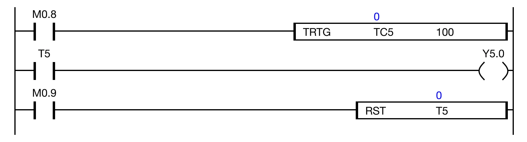
When the contact M0.8 is powered ON, the data register TC.5 counts down from 100.
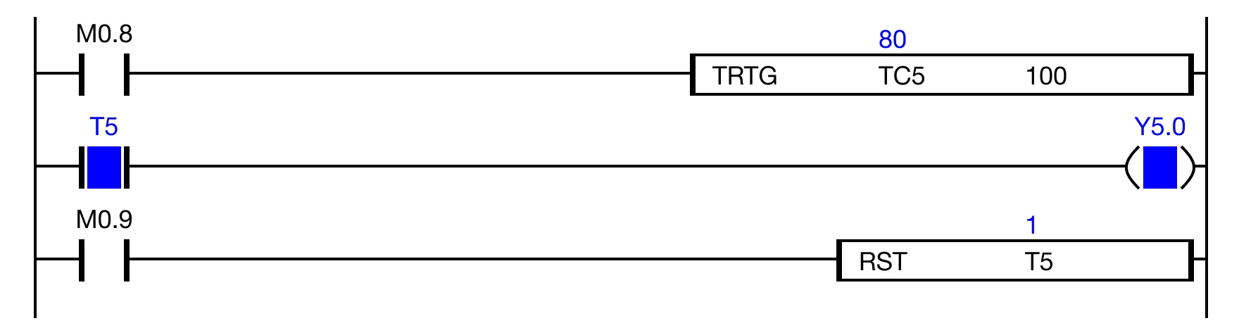
While the data register TC.5 counts down, the timer contact T.5 is powered ON. As a result, the coil Y5.0 is energized.
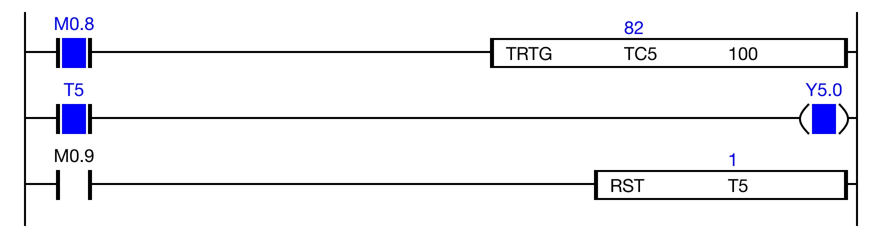
If the contact M0.8 is powered OFF then powered ON while the data register TC.5 is counting down, the timer will reset to 100 and count down from 100 again.
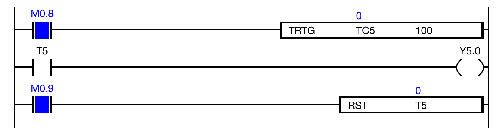
When the value of the data register TC.5 is 0, the timer contact T.5 is powered OFF, and the coil Y4.0 is deenergized.
Memory Monitor
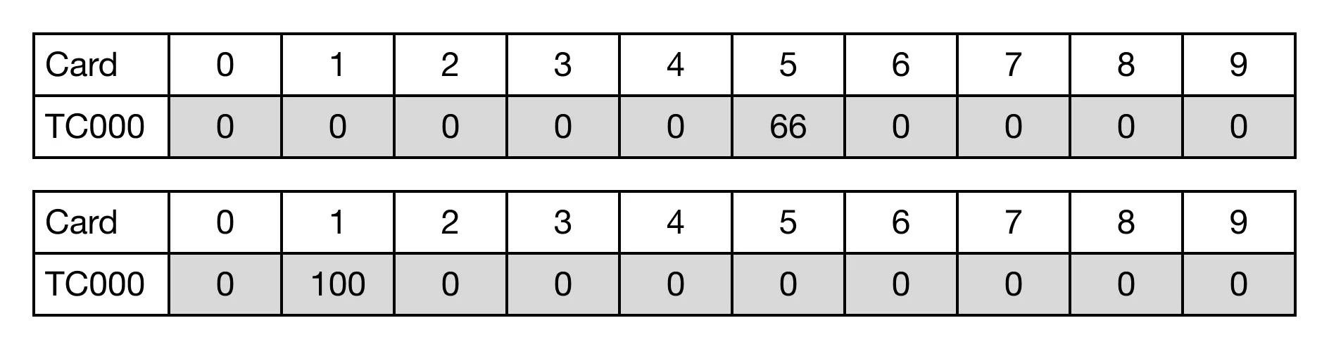
This is the result of the data register TC.5 counting down to 0.
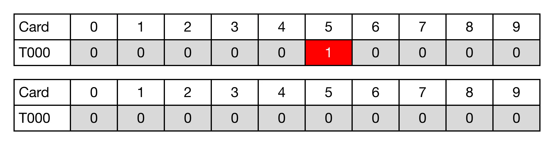
This is the result of the timer contact T.5 once the value of TC.5 is 0.