Instruction Parameters
Supported PLC Series
| PLC-AES | PLC-FB | PLC-ES |
|---|---|---|
| ✓ | ✓ | ✓ |
Supported Positioning Modules
| PLC-ES Series |
|---|
| PLC-ES0808P |
| PLC-ES1616P |
| MOD-SPOS02 |
Supported Data Registers
| M | X | Y | K | L | F | T | C | S | Z | R | Q | D | @D | Constant | |
|---|---|---|---|---|---|---|---|---|---|---|---|---|---|---|---|
| Base/Slot | ✓ | ✓ | ✓ | ✓ | ✓ | ✓ | ✓ | ✓ | – | ✓ | – | ✓ | ✓ | ✓ | ✓ |
| S | ✓ | ✓ | ✓ | ✓ | ✓ | – | – | – | – | ✓ | – | ✓ | ✓ | ✓ | ✓ |
| D | ✓ | – | ✓ | ✓ | ✓ | – | – | – | – | ✓ | – | ✓ | ✓ | ✓ | – |
Supported Flags
| Flag | Bit | Support |
|---|---|---|
| Error | F11.0 | ✓ |
| Zero | F11.1 | – |
| Carry | F11.2 | – |
Number of Steps
| Steps |
|---|
| 4 |
Operands
| Operand | Description |
|---|---|
| Base/Slot | The first operand. Entries are Hexadecimal data registers or constants. This is the base and slot number where the positioning module is located. This location depends on the amount of expansion modules the chassis contains. If the CPU supports positioning, refer below. |
| S | The second operand. Entries are WORD data registers or constants. This is where the control data is stored. For value ranges, refer below. |
| D | The third operand. Entries are only WORD data registers. This is where the result of the operation status is stored. |
Assignment Example
The following example shows how to assign values to Base/Slot.
Module/Slot (PLC-AES/ES)
| Module | Slot | Example |
|---|---|---|
| CPU | Slot 0 | H0000 or 0 |
| 1st Expansion | Slot 1 | H0001 or 1 |
| 5th Expansion | Slot 5 | H0005 or 5 |
| 10th Expansion | Slot 10 | H000A |
| 15th Expansion | Slot 15 | H000F |
PLC-ES CPU
If the CPU module is a PLC-AES or PLC-ES CPU, assign H0000 to Base/Slot.
S
| Control Data | PLC-ES0808P | PLC-ES1616P MOD-SP02POS |
|---|---|---|
| Positioning Data Number | 1 ~ 30 | 1 ~ 30 |
| Machine Original Point Return (OPR) | – | 9001 |
| Fast Original Point Return (OPR) | – | 9002 |
| Change Current Coordinate Value | – | – |
| Start Multiple Axes Simultaneously | – | – |
D Data Register Result
| Result Type | Bits | Description |
|---|---|---|
| Error Code | H00 | No error |
| Error Code | H01 | Command not found |
| Error Code | H10 | Incorrect positioning control data |
| Error Code | H80 | Axis error |
| Error Code | HFF | Instruction not supported |
| Operation Status | Bit 0 | 1 when the instruction executes |
| Operation Status | Bit 1 | 1 when instruction execution finishes |
| Operation Status | Bit 2 | 1 when an error occurs Simultaneously sets with Bit 1 |
| Operation Status | Bit 3 ~ 7 | Reserved |
Notice
Error Flag (F11.0) Notice
The error flag, F11.0, will be ON for one scan when the address of the data register assigned by @D exceeds the range of the data register, D. The range of the data register, D, is dependent on the CPU type.
Execution Condition
It is recommended that the PSTRT1 and PSTRT2 instructions be used with a pulse contact as an execution condition.
Instruction Usage
PSTRT1 controls the X axis. PSTRT2 controls the Y axis.
Ladder Diagram Examples
PSTRT1

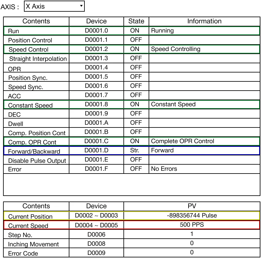
The PSTRT1 instruction controls the motion of the X-axis on the positioning module, Base/Slot. The control data, S, defines the control motion of the X-axis and saves the operation status in the assigned WORD data register, D.

When the contact, M0.0, is powered ON (1), the PSTRT1 instruction controls the X-axis’ motion. The operation result is saved in the data register, D30.

Memory Monitor

Program Monitor
PSTRT2

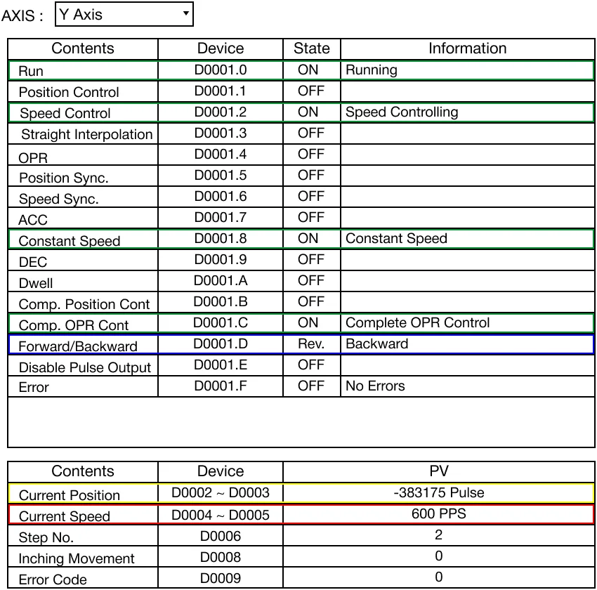
The PSTRT2 instruction controls the motion of the Y-axis on the positioning module, Base/Slot. The control data, S, defines the control motion of the Y-axis and saves the operation status in the assigned WORD data register, D.

When the contact, M0.0, is powered ON (1), the PSTRT2 instruction controls the Y-axis’ motion. The operation result is saved in the data register, D40.

Memory Monitor

Program Monitor