
Instruction Parameters
Supported PLC Series
| PLC-AES | PLC-FB | PLC-ES |
|---|---|---|
| ✓ | ✓ | ✓ |
Supported Data Registers
| M | X | Y | K | L | F | T | C | S | Z | R | Q | D | @D | Constant | |
|---|---|---|---|---|---|---|---|---|---|---|---|---|---|---|---|
| n | – | – | – | – | – | – | – | – | – | – | – | – | – | – | ✓ |
Supported Flags
| Flag | Bit | Support |
|---|---|---|
| Error | F11.0 | – |
| Zero | F11.1 | – |
| Carry | F11.2 | – |
Number of Steps
| Steps |
|---|
| 2 |
Operands
| Operand | Description |
|---|---|
| n | The only operand. Entries are only constants. This is the branch ID to jump to. The value range is 0 ~ 127. |
Notice
Subroutine Usage
The JMP ~ JME or JMPP ~ JME instructions are used in a SBRT ~ RET block. The program may NOT use a jump statement inside a subroutine.
Instruction Behavior
The JMP and JMPP instructions behave as follows:
- JMP:
- When the execution condition of the JMP instruction is ON (1), the program jumps to the next step of the JME instruction within the identical branch ID, n.
- When the execution condition of the JMP instruction is OFF (0), the JMP instruction is not executed, and the program does not jump.
- When the JMP instruction is executed, all instructions between the JMP and JME instructions are NOT executed.
- Multiple JMP n instructions can be placed before their related JME n instruction.
- JMPP:
- When the execution condition of the JMPP instruction is ON (1), the program jumps to the next step of the JME instruction with a matching branch ID, n for 1 scan.
- When the execution condition of the JMPP instruction is OFF (0), the JMPP instruction is not executed and program does NOT jump.
- When the JMPP instruction is executed, all instructions between the JMPP and JME instructions are not executed for 1 scan.
Ladder Diagram Examples
JMP

The JMP instruction jumps to the corresponding JME instruction according to the branch ID, n, to execute the next instruction.
- The following are the execution conditions for the JMP, JMPP and JME instructions:
- The value range for the JMP n instruction is 0 ~ 127.
- The JMP n or JMPP n instructions cannot have the same ID number, n, as the SBRT instruction.
- All related JMP or JMPP instructions should be placed before their corresponding JME instruction.
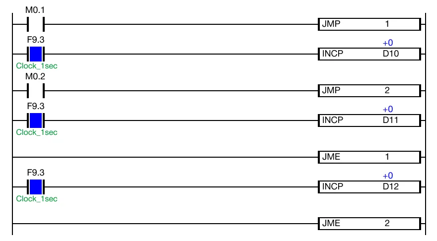
Notice
This example occurs in a SBRT ~ RET block.
Before the SBRT instruction is called using the CALL or CALLP instruction, the values of the data registers, D10, D11, and D12 do NOT increase using the INCP instruction.
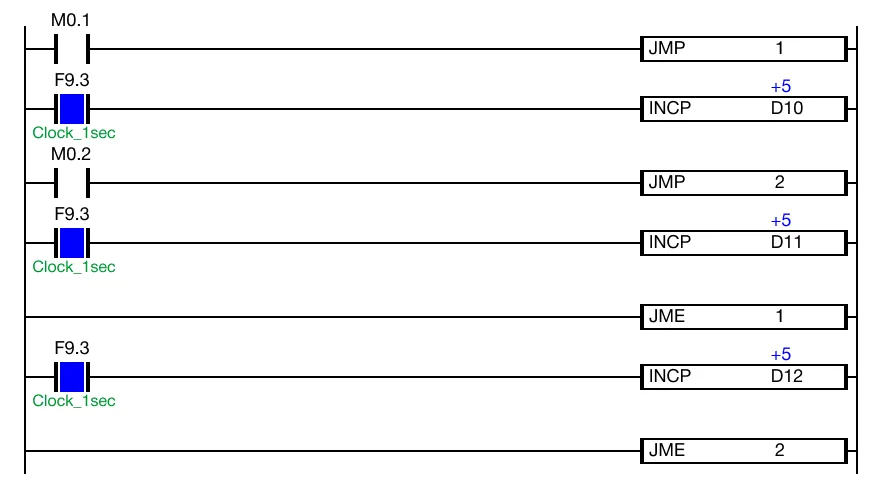
Once the SBRT instruction is called using the CALL or CALLP instruction, the values of the data registers, D10, D11, and D12 increase every 1 scan using the INCP instruction.
Energizing JMP 1
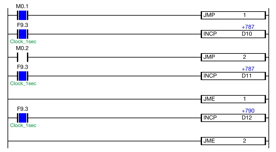
When the contact, M0.1, is powered ON (1), the JMP 1 instruction is energized. The values of the data registers, D10 and D11, no longer increase every 1 scan. The JMP 1 instruction will skip the following instructions starting at JMP 1 ~ JME 1. The value of the data register, D12, will continue to increase every 1 scan.
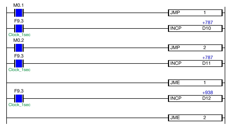
When the contacts, M0.1 and M0.2, are powered ON (1), the value of the data register, D12, will continue to increase every 1 scan. This is because JMP 1 ignores the JMP 2 execution call.
Energizing JMP 2
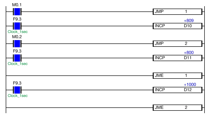
When the contact, M0.1 is powered OFF (0) and the contact, M0.2, is powered ON (1), the value of the data registers, D11 and D12, no longer increases every 1 scan. The values of the data registers, D11 and D12, no longer increase every 1 scan. The JMP 2 instruction will skip the following instructions starting at JMP 2 ~ JME 2. The value of the data register, D10, will increase every 1 scan.
JMPP

The JMPP one-shot instruction jumps to the corresponding JME instruction according to the branch ID, n, to execute the next instruction. Every time this instruction executes, it energizes the output only once.
- The following are the execution conditions for the JMP, JMPP and JME instructions:
- The value range for the JMP n instruction is 0 ~ 127.
- The JMP n or JMPP n instructions cannot have the same ID number, n, as the SBRT instruction.
- All related JMP or JMPP instructions should be placed before their corresponding JME instruction.
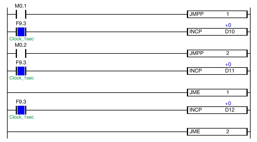
Notice
This example occurs in a SBRT ~ RET block.
Before the SBRT instruction is called using the CALL or CALLP instruction, the values of the data registers, D10, D11, and D12 do NOT increase using the INCP instruction.
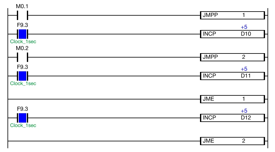
Once the SBRT instruction is called using the CALL or CALLP instruction, the values of the data registers, D10, D11, and D12 increase every 1 scan using the INCP instruction.
Energizing JMPP 1
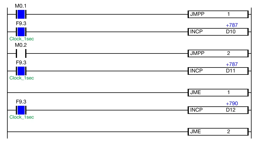
When the contact, M0.1, is powered ON (1), the JMPP 1 instruction is energized. The values of the data registers, D10 and D11, no longer increase every 1 scan. The JMPP 1 instruction will skip the following instructions starting at JMPP 1 ~ JME 1. The value of the data register, D12, will continue to increase every 1 scan.
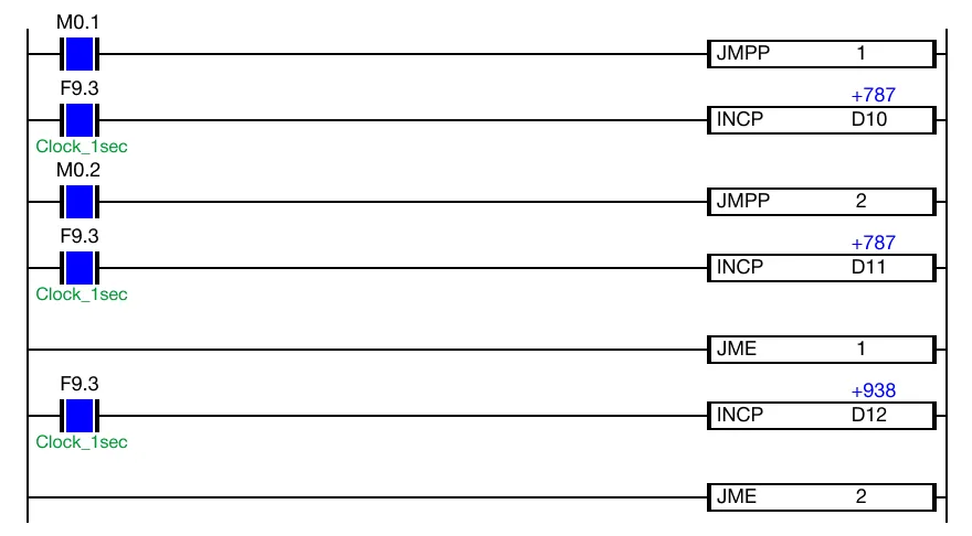
When the contacts, M0.1 and M0.2, are powered ON (1), the value of the data register, D12, will continue to increase every 1 scan. This is because JMPP 1 ignores the JMPP 2 execution call.
Energizing JMPP 2
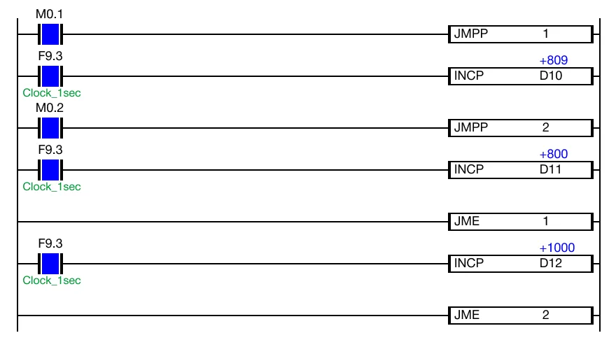
When the contact, M0.1 is powered OFF (0) and the contact, M0.2, is powered ON (1), the value of the data registers, D11 and D12, no longer increases every 1 scan. The values of the data registers, D11 and D12, no longer increase every 1 scan. The JMPP 2 instruction will skip the following instructions starting at JMPP 2 ~ JME 2. The value of the data register, D10, will increase every 1 scan.