
Connection Requirements
Supported PLC Series
| PLC-AES | PLC-FB | PLC-ES |
|---|---|---|
| ✓ | ✓ | ✓ |
Supported Data Registers
| M | X | Y | K | L | F | T | C | S | Z | R | Q | D | @D | Constant | |
|---|---|---|---|---|---|---|---|---|---|---|---|---|---|---|---|
| S | ✓ | ✓ | ✓ | ✓ | ✓ | ✓ | ✓ | ✓ | ✓ | – | – | ✓ | ✓ | – | – |
Supported Flags
| Flag | Bit | Support |
|---|---|---|
| Error | F11.0 | – |
| Zero | F11.1 | – |
| Carry | F11.2 | – |
Number of Steps
| Steps |
|---|
| 1 |
Operands
| Operand | Description |
|---|---|
| S | This is the BOOL data register. This is the bit number to toggle the contact ON/OFF. When the bit is 0, the contact is OFF. When the bit is 1, the contact is ON. |
Notice
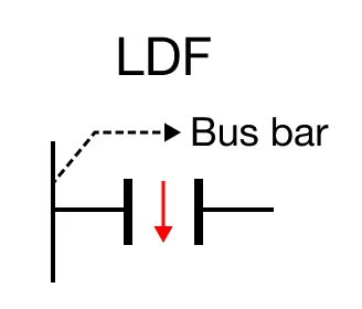
Contact Orientation
The LDF falling edge (one-shot) contact orientation behaves as follows: – The LDF falling edge (one-shot) contact orientation is ON for 1 scan only. – The one-shot contact is ON at the falling edge of the assigned BOOL data register. – The one-shot contact turns ON when the assigned BOOL data register goes from OFF to ON.
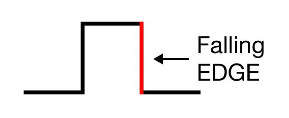
The one-shot contact turns ON on the falling edge of an input signal or condition.
Ladder Diagram Examples
LD Gate Example
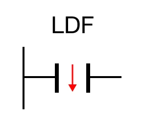
The LDF falling edge (one-shot) contact orientation creates an execution condition based on the ON status of the assigned BOOL data register, S, for only 1 scan.

When the falling edge (one-shot) contact, M24.5, is powered OFF, the coil, Y3.3, is deenergized.

When the falling edge (one-shot) contact, M24.5, is powered ON, the coil, Y3.3, is energized for only 1 scan.

The falling edge (one-shot) contact, M24.5, will remain OFF (unless otherwise specified) after being powered, but the coil, Y3.3, is deenergized after 1 scan.
Scan Execution Time
Since scan programs execute in less than a second, it might not appear that the coil, Y3.3, was energized.