
High-Speed Counter for PLC-ES Special Program Parameters
- The high-speed counter parameters take up 26 WORDs for memory.
- The memory location can be configured for the M, L, K, and D data registers.
- Please refer to the configuration page for setup help.
- The parameters of each channel are allocated from the starting address to the order described in the table below.
- Unless an item says Read Only, the item can have a value read from or written to that data register.
High-Speed Counter Parameters
| CH 1 Offset | CH 2 Offset | Item | Config. Value | Config. Function | Memory | Note |
|---|---|---|---|---|---|---|
| 0 | +26 | Count Mode | H0000 | Linear Counter | WORD | Read Only |
| 0 | +26 | Count Mode | H0001 | Ring Counter | WORD | Read Only |
| +1 | +27 | Input Pulse Type | H0000 | 2-Phase 2-Multiplication 2-Input | – | – |
| +1 | +27 | Input Pulse Type | H0001 | 2-Phase 4-Multiplication 2-Input | – | – |
| +1 | +27 | Input Pulse Type | H0002 | 1-Phase 2-Multiplication Low Active | – | – |
| +1 | +27 | Input Pulse Type | H0003 | 1-Phase 2-Multiplication High Active | – | – |
| +2 | +28 | Compare Mode | H0000 | Less Than < | WORD | – |
| +2 | +28 | Input Pulse Type | H0001 | Less Than Equal To ≤ | WORD | – |
| +2 | +28 | Input Pulse Type | H0002 | Equal To = | WORD | – |
| +2 | +28 | Input Pulse Type | H0003 | Greater Than Equal To ≥ | WORD | – |
| +2 | +28 | Input Pulse Type | H0004 | Greater Than > | WORD | – |
| +2 | +28 | Input Pulse Type | H0005 | Inclusive <> | WORD | – |
| +2 | +28 | Input Pulse Type | H0006 | Exclusive >< | WORD | – |
| +3 | +29 | Internal Preset Value | – | -2,147,483,648 ~ 2,147,483,647 (232) | DWORD | Low WORD |
| +4 | +30 | Internal Preset Value | DWORD | High WORD | ||
| +5 | +31 | External Preset Value | – | -2,147,483,648 ~ 2,147,483,647 (232) | DWORD | Low WORD |
| +6 | +32 | External Preset Value | DWORD | High WORD | ||
| +7 | +33 | Ring Counter Maximum Value | – | -2,147,483,648 ~ 2,147,483,647 (232) | DWORD | Low WORD |
| +8 | +34 | Ring Counter Maximum Value | DWORD | High WORD | ||
| +9 | +35 | Compare Maximum | – | -2,147,483,648 ~ 2,147,483,647 (232) | DWORD | Low WORD |
| +10 | +36 | Compare Maximum | DWORD | High WORD | ||
| +11 | +37 | Compare Minimum | – | -2,147,483,648 ~ 2,147,483,647 (232) | DWORD | Low WORD |
| +12 | +38 | Compare Minimum | DWORD | High WORD | ||
| +13 | +39 | Compare Output | HFFFF | Reserved | WORD | – |
| +13 | +39 | Compare Output | H0000 | Y0010 | WORD | – |
| +13 | +39 | Compare Output | H0001 | Y0011 | WORD | – |
| +13 | +39 | Compare Output | H0002 | Y0012 | WORD | – |
| +13 | +39 | Compare Output | H0003 | Y0013 | WORD | – |
| +13 | +39 | Compare Output | H0004 | Y0014 | WORD | – |
| +13 | +39 | Compare Output | H0005 | Y0015 | WORD | – |
| +13 | +39 | Compare Output | H0006 | Y0016 | WORD | – |
| +13 | +39 | Compare Output | H0007 | Y0017 | WORD | – |
| +14 | +40 | Unit Time | 1 ~ 60,000ms | – | – | |
| +15 | +41 | Pulse/Rotation | 1 ~ 60,000pulses | – | – |
High-Speed Counter Control
| CH 1 Offset | CH 2 Offset | Item | Config. Value | Config. Function | Memory | Note |
|---|---|---|---|---|---|---|
| +16 | +42 | Counter | Bit 0 | Enable: 1 Disable: 0 | WORD | – |
| +16 | +42 | Internal Preset | Bit 1 | Preset: 1 No Preset: 0 | WORD | – |
| +16 | +42 | Externaml Preset | Bit 2 | Enable: 1 Disable: 0 | WORD | – |
| +16 | +42 | Count | Bit 3 | Up: 0 Down: 1 | WORD | Read Only |
| +16 | +42 | Compare Output | Bit 4 | Enable: 1 Disable: 0 | WORD | Read Only |
| +16 | +42 | Select RPM/PPS | Bit 5 | PPS: 0 RPM: 1 | WORD | – |
| +16 | +42 | Latch Counter | Bit 6 | Enable: 1 Disable: 0 | WORD | Read Only |
High-Speed Counter Monitor
| CH 1 Offset | CH 2 Offset | Item | Config. Value | Config. Function | Memory | Note |
|---|---|---|---|---|---|---|
| +17 | +43 | RPM/PPS Measured Value | -2,147,483,648 ~ 2,147,483,647 (232) | |||
| +18 | +44 | RPM/PPS Measured Value | ||||
| +19 | +45 | Reserved | Reserved | Reserved | Reserved | – |
| +20 | +46 | Carry | Bit 0 | Carry: 1 No Carry: 0 | WORD | |
| +20 | +46 | Borrow | Bit 1 | Borrow: 1 No Borrow: 0 | WORD | |
| +20 | +46 | Compare Result | Bit 2 | Result: 1 No Result: 0 | WORD | |
| +21 | +47 | Current Count Value | -2,147,483,648 ~ 2,147,483,647 (232) | DWORD | ||
| +22 | +48 | Current Count Value | DWORD | |||
| +23 | +49 | Input Pulse per Unit Time | -2,147,483,648 ~ 2,147,483,647 (232) | DWORD | ||
| +24 | +50 | Input Pulse per Unit Time | DWORD | |||
| +25 | +51 | Error Code | Refer to the Error Code Table | WORD |
Count Mode
- Ring or linear counting can be chosen.
- If the mode is changed from ring to linear or linear to ring while operating, the Counter flag must be enabled again.
- Until the Counter flag is enabled again, operation will continue with the previous counting mode.
- If the mode is changed from ring to linear or linear to ring while operating, the Counter flag must be enabled again.
- If the count mode is switched from linear to ring counting and the current value exceeds the ring counter range, linear counting will operate.
Input Pulse Type
- 2-Phase encoder input signals are supported.
- 1-Phase
- 2-Phase
- The multiplication type can be selected.
- 1-Phase
- 2-Multiplication (Low active)
- 2-Multiplication (High active)
- 2-Phase
- 1-Multiplication
- 2-Multiplication
- 4-Multiplication
- 1-Phase
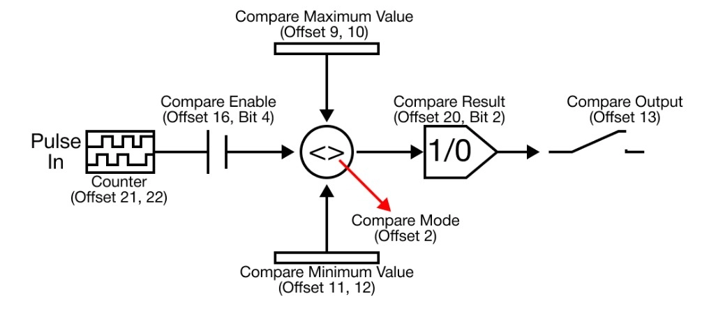
Compare Mode
- The compare mode is activated only when the compare output flag is enabled.
- There are 7 compare modes offered by the high-speed counter.
- Less than (<)
- Less than equal to (≤)
- Equal to (=)
- Greater than equal to (≥)
- Greater than (>)
- Inclusive (<>)
- Exclusive (><)
- The result of a comparison can be found in the sequence program under compare output flag.
- If the output contact at the compare output contact (offset +13 or +39) is specified, the comparison can be directly output as an electrical signal.
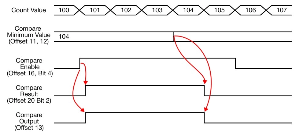
Mode 0 – Less Than (Current Value < Compare Minimum Value)
- When the currently-counted value is less than the compare output minimum value, the output is turned ON.
- When the currently-counted value increases and becomes equal or greater than the compare minimum value, the output is turned OFF.
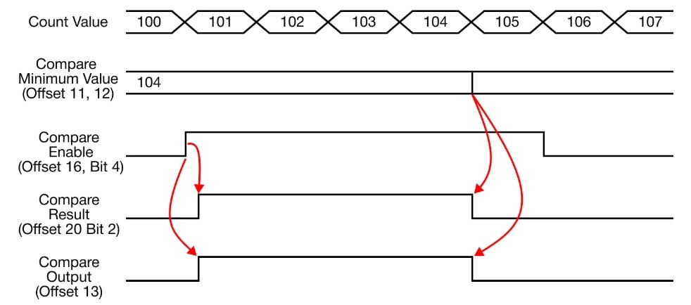
Mode 1 – Less Than Equal To (Current Value ≤ Compare Minimum Value)
- When the currently-counted value is less than or equal to the compare output minimum value, the output is turned ON.
- When the currently-counted value increases and becomes greater than the compare minimum value, the output is turned OFF.
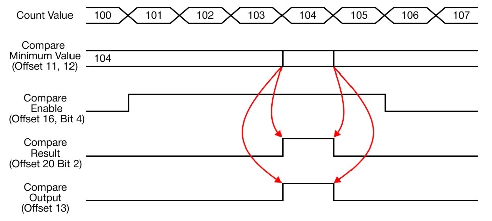
Mode 2 – Equal To (Current Value = Compare Minimum Value)
- When the currently-counted value is equal to the compare output minimum value, the output is turned ON.
- When the currently-counted value changes in relation to the compare minimum value, the output is turned OFF.
Mode 3 – Greater Than Equal To (Current Value ≥ Compare Minimum Value)
- When the currently-counted value is greater than or equal to the compare output minimum value, the output is turned ON.
- When the currently-counted value decreases and becomes less than the compare minimum value, the output is turned OFF.
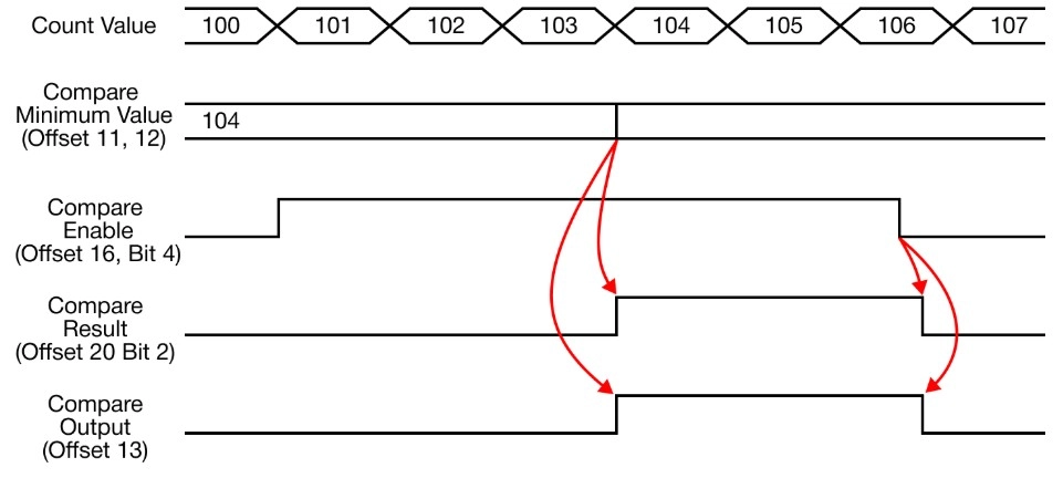
Mode 4 – Greater Than (Current Value < Compare Minimum Value)
- When the currently-counted value is greater than the compare output minimum value, the output is turned ON.
- When the currently-counted value decreases and becomes equal or less than the compare minimum value, the output is turned OFF.
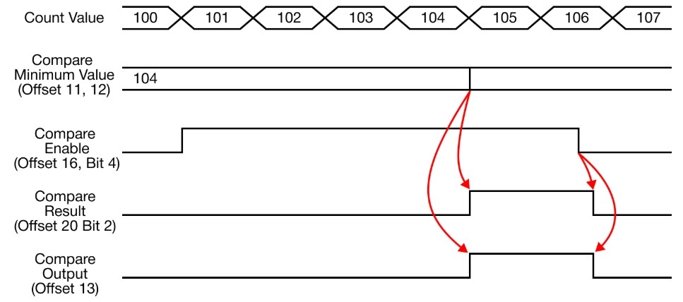
Mode 5 – Inclusive (Compare Minimum Value ≤ Current Value ≤ Compare Maximum Value)
- When the currently-counted value is included between the minimum and maximum compare values, the output is turned ON.
- When the currently-counted value is not included between the minimum and maximum compare values, the output is turned OFF.
- It is not necessary to specify the compare value maximum to a value greater than the minimum compare value.
- Given two values, the PLC internally takes the larger of the two values as maximum and less as minimum.
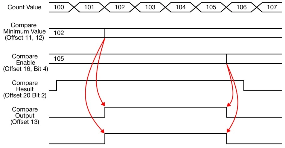
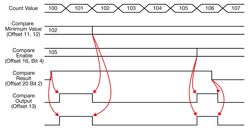
Mode 6 – Exclusive (Compare Minimum Value > Current Value, Current Value > Compare Maximum Value)
- When the currently-counted value is not included between the minimum and maximum compare values, the output is turned ON.
- When the currently-counted value is included between the minimum and maximum compare values, the output is turned OFF.
- It is not necessary to specify the compare value maximum to a value greater than the minimum compare value.
- Given two values, the PLC internally takes the larger of the two values as maximum and less as minimum.
Internal Preset Value
- When the internal preset command (offset +16 or +42) is switched from the reset to set status (0 to 1), specify the currently-counted value as a designated value in this offset.
- If ring counting and the specified value is out of the count range, the current value will not be modified despite the preset command.
- Error Code 100 occurs
- If ring counting and the specified value is out of the count range, the current value will not be modified despite the preset command.
External Preset Value
- When the external preset signal (Xn.4 or Xn.6) is changed (contact A) from OFF to ON, the currently-counted value is changed to a designated value in this offset (+5 and +6 or +31 and +32).
- If ring counting and the specified value is out of the count range, the current value will not be modified despite the preset command.
- Error Code 100 occurs
- If ring counting and the specified value is out of the count range, the current value will not be modified despite the preset command.
Ring Counter Maximum Value
- When the count mode is set to ring count, 1, the value set in the ring counter maximum value will be taken as the upper limit.
- The count range of the ring counter is from 0 ~ user-defined maximum value.
- If the increasing pulses are pulsed when the ring counter reaches the maximum value, the count value will be automatically reset to 0.
- The carry flag (offset +20 or +45, bit 1) will be set to 1.
- If the decreasing pulses are pulsed when the ring counter reaches the value of 0, the count will be changed to the ring counter maximum value.
- The carry flag (offset +20 or +45, bit 2) will be set to 1.
Compare Minimum & Maximum Values
- The comparison calculation process, that is performed when the compare out flag (offset +16 or +42) is ON, uses the setting value in this offset.
- Either the compare minimum value (offset +11 and +12 or +37 and +38) only or both the minimum and maximum compare values can be used together.
- It is not necessary to specify the compare value maximum to a value greater than the minimum compare value.
- Given two values, the PLC internally takes the larger of the two values as maximum and less as minimum.
Compare Output
- The carry flag (offset +20 or +45, bit 2) can be used as an internal flag, and it can also be used to output an electrical signal.
- In order to use this function, one of the outputs from Y0010 ~ Y0017 must be selected.
- Do not operate the assigned output contact in the sequence program.
- In order to use this function, one of the outputs from Y0010 ~ Y0017 must be selected.
- If there is a duplicate contact used in the sequence program, it may not work properly.
- *Ensure the compare output flag (offset +16 or +42, bit 4) is ON.
Unit Time
- Unit time must be ON in order to use and measure rotations per minute (RPM) or pulses per second (pps).
- If unit time is 0, the RPM and PPS measurement function will not operate.
- By measuring the pulse count number for a specified period of time and based on the configured values, then the measured pulse count number will be written to the input pulse per unit time (offset +23 and +24 or +49 and +50).
- The measured value will be updated in the unit time interval.
Pulse per 1 Cycle/Rotation
- In order to measure rotations per minute (RPM), the offset (+15 or +41) must be configured as a non-zero value.
- If the value is 0, pulses per second (PPS) will operate in the measurement mode.
- Error Code 101 will appear regardless of the *RPM/PPS selection (offset +16 or +42, Bit 5).
- If the value is 0, pulses per second (PPS) will operate in the measurement mode.
Counter Operation Setting
- Select the channel to be used:
- Channel 1: offset +16, bit 0
- Channel 2: offset +42, bit 0
- To enable counting, set bit 0 to 1.
Internal Preset Operation Setting
- To forcefully set the currently-counted value to a specific value, set bit 1 to 1.
- Channel 1: offset +16, bit 1
- Channel 2: offset +42, bit 1
- When this bit is ON, the current count value (offset +21 and +22 or +47 and +48) is written as this value.
- It is not possible to use the DMOV instruction to modify the currently-counted value.
- The built-in high-speed counter only operates to write the internal counter value for every scan.
- It is not possible to use the DMOV instruction to modify the currently-counted value.
External Preset Operation Setting
- To forcefully set the currently-counted value to a specific external value, set bit 2 to 1.
- Channel 1: offset +16, bit 2
- Channel 2: offset +42, bit 2
- The external value comes from an external signal.
- The signal must be received by the input signal contacts (Xn.4 or Xn.6).
- The preset setup value must be written to the external preset value (offset +5 and +6 or +31 and +32) before the preset signal is pulsed.
Count Operation Setting
- The currently-counted value increases or decreases by the input signal direction (phase difference).
- To count up, offset +16 or 42, bit 3, must be OFF.
- To count down, offset +16 or 42, bit 3, must be ON.
Compare Output Operation Setting
- The high-speed counter can output by comparing the currently-counted value to the comparison value.
- Select 1 of the 7 compare modes to compare the values.
- If the flag (offset +16 or +42, bit 3), is OFF, the comparison function will not operate regardless of other configurations.
Select RPM/PPS Operation Setting
- Rotations per minute (RPM) or pulses per second (PPS) are stored in the measured value offset (+17 and +18 or +43 and +44).
- To enable RPM measurement, set bit 5 to 1:
- Channel 1: offset +16, bit 5
- Channel 2: offset +42, bit 5
- To enable PPS measurement, set bit 5 to 0:
- Channel 1: offset +16, bit 5
- Channel 2: offset +42, bit 5
- For RPM measurement, the pulse/rotation value must be greater than 0.
- Otherwise, PPS will be measured.
Latch Counter Operation Setting
- To retain the currently-counted value, even if the power turns off, turn bit 6 to 1.
- Channel 1: offset +16, bit 6
- Channel 2: offset +42, bit 6
- The currently-counted value is stored in non-volatile memory.
RPM/PPS Measured Value
- The measured value (offset +17 and +18 or +43 and +44) will store the measured rotations per minute (RPM) or pulses per second (pps) value.
- For RPM measurement, the pulse/rotation value must be greater than 0.
- Otherwise, PPS will be measured.
Carry Monitor
- The carry flag (offset +20 or +45, bit 0) will be ON in the following conditions:
- When additional pulses (counting up) are detected after reaching the maximum value, 2,147,483,647, while linear counting.
- When an additional pulse input is detected at the ring counter maximum value (offset +7 and +8 or +23 and +24).
- The count value becomes 0 and carry signal occurs.
- If condition 2 occurs, the operation will behave as follows:
- Linear counting: stops the increasing direction count and displays the fixed maximum value.
- When the decreasing direction pulse is pulsed, the decrementing count works normally.
- Unit Time: if unit time (ms) is 0, the rotations per minute (RPM) and pulses per second (pps) functions will not operate.
- Neither count function of the input pulse will operate.
- Linear counting: stops the increasing direction count and displays the fixed maximum value.
- The carry signal will be reset 0 under the following conditions:
- When the increasing direction pulse is input.
- When it is forcefully reset by the sequence program.
Borrow Monitor Flag
- The borrow flag (offset +20 or +45, bit 1) will be ON in the following conditions:
- When additional pulses (counting down) are detected after reaching the minimum value, -2,147,483,648, while linear counting.
- When an additional pulse input is detected at the ring counter maximum value (offset +7 and +8 or +23 and +24).
- The count value becomes 0 and borrow signal occurs.
- If condition 2 occurs, the operation will behave as follows:
- Linear counting: stops the increasing direction count and displays the fixed maximum value.
- When the decreasing direction pulse is pulsed, the decrementing count works normally.
- Ring counting: currently-counted value will be switched to the ring counter maximum value (offset +7 and +8 or +23 and +24).
- The normal counting operation proceeds according to the direction of the input pulse.
- Linear counting: stops the increasing direction count and displays the fixed maximum value.
- The borrow signal will be reset 0 under the following conditions:
- When the increasing direction pulse is input.
- When it is forcefully reset by the sequence program.
Compare Output Monitor Flag
- The compare output flag (offset +20 or +45, bit 1) will be ON if the *compare output (offset +16 or +32, bit 4) is ON.
- The comparison operation with the currently-counted value is performed based on the configured comparison value.
- The result is written into this flag.
- The comparison operation with the currently-counted value is performed based on the configured comparison value.
- When it is configured to output the comparison result as a contact, it indicates the same status as compare output (offset +13 or +29).
Current Count Value
- This is the currently-counted value.
- To force this value to change, use the internal preset value or external preset value function.
Input Pulse per Unit Time
- During the unit time (offset +14 or +30), the number of the input pulse will be recorded.
- If the unit time (offset +14 or +30) is set to 0, the number of pulses can’t be measured.
- This flag will also result in 0.
Error Code
| Code | Error Name | Description |
|---|---|---|
| 0 | No Error | Normal operation mode |
| 100 | Exceeded Ring Counting Range | Currently-counted value exceeds the ring counting range |
| 101 | RPM Operation Error | When the Pulse/Rotation Vyvle is set to 0. |