
Serial Protocol Communication Program
The Serial Protocol program allows users to define and configure the communication frame of the serial communication module manually.
Register Serial Protocol Program
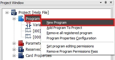
Step 1: To create a new serial protocol program, in the Project Window, right-click Program and left-click New Program.
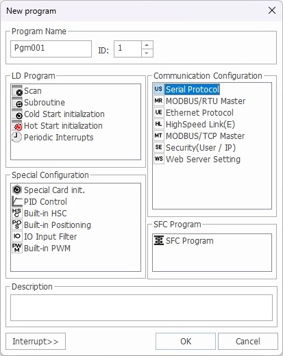
Step 2: Left-click Serial Protocol and left-click OK.
Write Program
- The following example demonstrates writing a program to read five WORDs from %MW100 of another branded PLC and store them in five WORDs starting from D100 of a Maple Systems PLC.
- The communication uses Channel #1 (RS-232).
Program Configuration
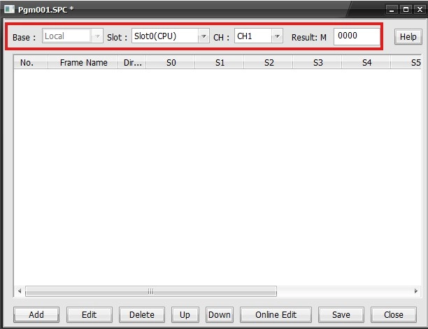
| Item | Descirption |
|---|---|
| Base | Module Mounted Base |
| Slot | Module Mounted Slot |
| CH | Serial Communication Channel |
| Result: M | Starting M Data Register |
Frame Configuration
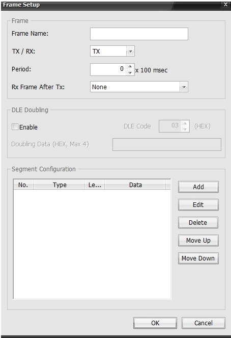
| Item | Description |
|---|---|
| Frame Name | Name of the frame |
| TX/RX | TX: Transmit the frame RX: Receive the frame |
| Period | The interval between sending/receiving the frame |
| Rx Frame After Tx | Specifies the frame that corresponds to the response |
| Add | Defines and adds a new segment |
| Edit | Edits and existing segment |
| Delete | Delete the existing segment |
| Move Up | Moves the selected segment up |
| Mode Down | Moves the selected segment down |
- To reposition a frame, type CTRL + X to remote it, navigate to the desired position and type CTRL + V.
Frame Set Up
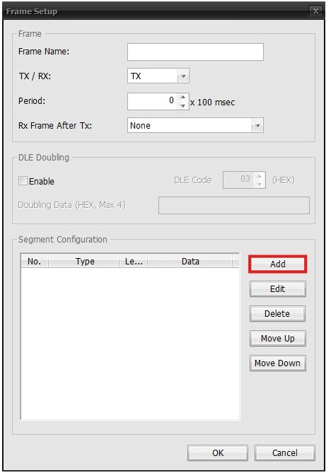
- To add a new frame, left-click Add.
Segment Configuration – Receiving Frame
- RX frame of the continuous read command for the direct variable.
- The receiving frame defines the frame contents to interpret from the response frame for the continuous read requesting frame of the other PLC’s direct variable.
Header
- This will set the header for the protocol.
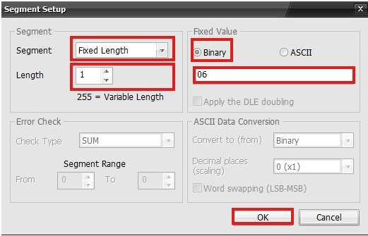
- Set the Segment type to Fixed Length, Length to 1, and the Binary to 06.
- The header for the ACK response from is ACK (O6H).
Station Number
- The station number sets the area for the protocol.
- Enter the station number of the other PLC.
- In this example, the station number is 01H (1).
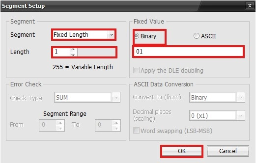
- Set the Segment type to Fixed Length, Length to 1, and the Binary to 01.
Command & Command Type
- Continuous read command for the direct variable + command type rSB (r + SB).
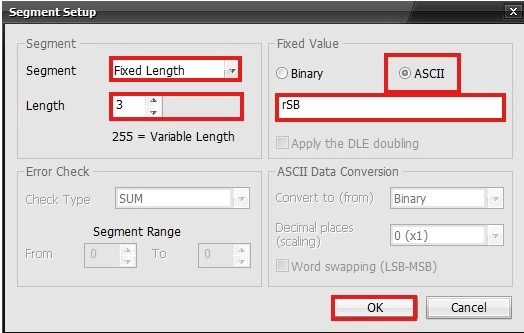
- Set the Segment type to Fixed Length, Length to 3, and the ASCII to rSB.
Number of Blocks & Data
- The number of blocks is 1.
- The number of data is 10.
- (= 5 WORDs ×2, 0AH) → (01 + 0A)
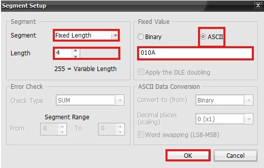
- Set the Segment type to Fixed Length, Length to 4, and the ASCII to 010A.
Data
- 5 WORDs will be received from the Glofa PLC starting at D100 (MapleLogic).
- To display 5 WORDs as an ASCII code: 20 bytes = (5 WORDs × 4 characters)
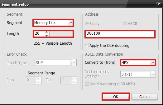
- Set the Segment type to Memory Link, Length to 20, Address to D00100, and the Convert to (from) to HEX.
Tail
- The tail of the ACK frame is ETX (03H).
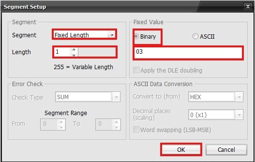
- Set the Segment type to Fixed Length, Length to 1, and the Binary to 03.
BCC
- BCC is the ASCII-converted value of the lowest 1 byte from the ASCII value that adds from the header to the tail.
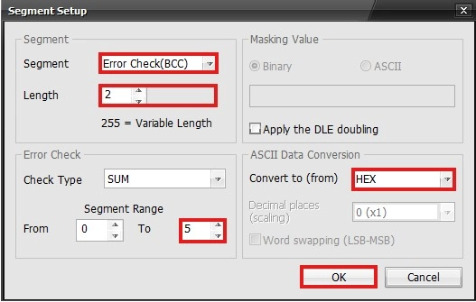
- Set the Segment type to Error Check(BCC), Length to 2, Segment Range to 0 ~ 5, and the Convert to (from) to HEX.
Result
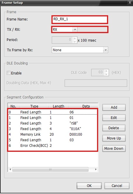
- This is the result of the receiving frame.
Segment Configuration – Transmitting Frame
- The transmitting frame for the continuous read command of the direct variable.
- This defines the request frame of the continuous read command for the direct variable.
Header
- The header of the request frame is ENQ (05H).
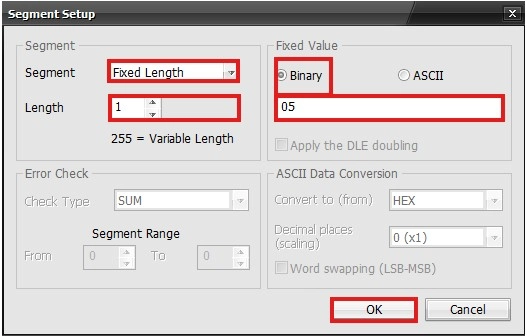
- Set the Segment type to Fixed Length, Length to 1, and the Binary to 05.
Station Number
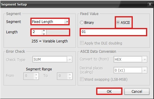
- Set the Segment type to Fixed Length, Length to 2, and the ASCII to 01.
Command & Command Type
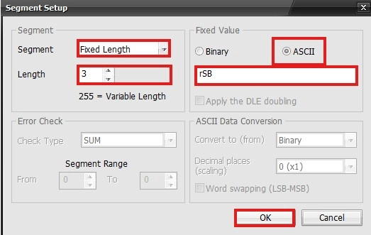
- Set the Segment type to Fixed Length, Length to 3, and the ASCII to rSB.
Variable Length, Name, and Data
- The variable length is 6 bytes (06H).
- The direct variable is %MW100%.
- The number of WORDs is 5 (05H).
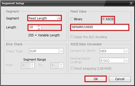
- Set the Segment type to Fixed Length, Length to 10, and the ASCII to 06%MW10005.
Tail
- The tail of the ACK frame is EOT (04H).
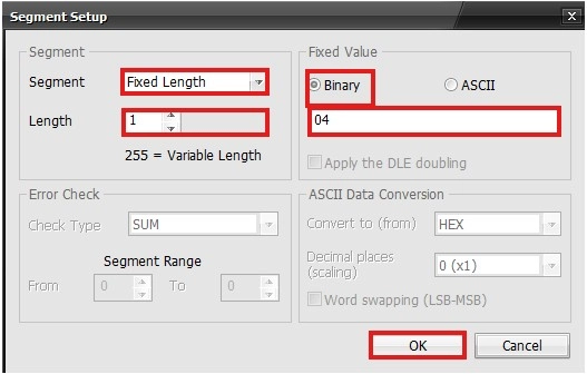
- Set the Segment type to Fixed Length, Length to 1, and the Binary to 04.
BCC
- BCC is the ASCII-converted value of the lowest 1 byte from the ASCII value that adds from the header to the tail.
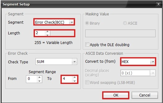
- Set the Segment type to Error Check(BCC), Length to 2, Segment Range to 0 ~ 4, and the Convert to (from) to HEX.
Result
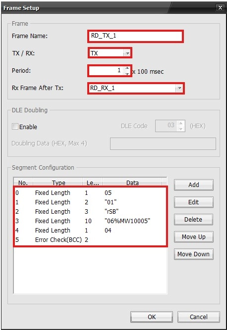
- This is the result of the transmitting frame.
Frames
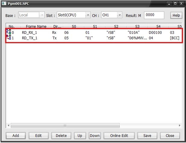
- The receiving and transmitting frames will be displayed in the special program.