Connection Requirements
Supported PLC Series
| PLC-AES | PLC-FB | PLC-ES |
|---|---|---|
| ✓ | ✓ | ✓ |
Supported Data Registers
| M | X | Y | K | L | F | T | C | S | Z | R | Q | D | @D | Constant |
|---|---|---|---|---|---|---|---|---|---|---|---|---|---|---|
| – | – | – | – | – | – | – | – | – | – | – | – | – | – | – |
Supported Flags
| Flag | Bit | Support |
|---|---|---|
| Error | F11.0 | – |
| Zero | F11.1 | – |
| Carry | F11.2 | – |
Number of Steps
| Steps |
|---|
| 1 |
Notice
General Connection Behavior
The branching connections behave as follows:
- Multiple branch connections are used to connect output coils to the left-hand side of a contact.
- Without multiple branch connections, connections can only be made to the right-hand side of the last contact.
- For every MPS connection, there must be a corresponding MPP connection.
- The last contact or coil circuit must be connected by a MPP connection.
Multiple Point Store Behavior
The MPS branch connection behaves as follows:
- MPS is NOT displayed in the ladder diagram.
- MPS stores the preceding operation result (ON or OFF) preceding the MPS.
- The connection performs the operation with the resulting value in the next step.
- MPS can be used successively up to 16 connection.
- MPS is used to start branching in a ladder.
- MPS stores the connection point of the ladder circuit so that further coil branches can recall the value later.
Example
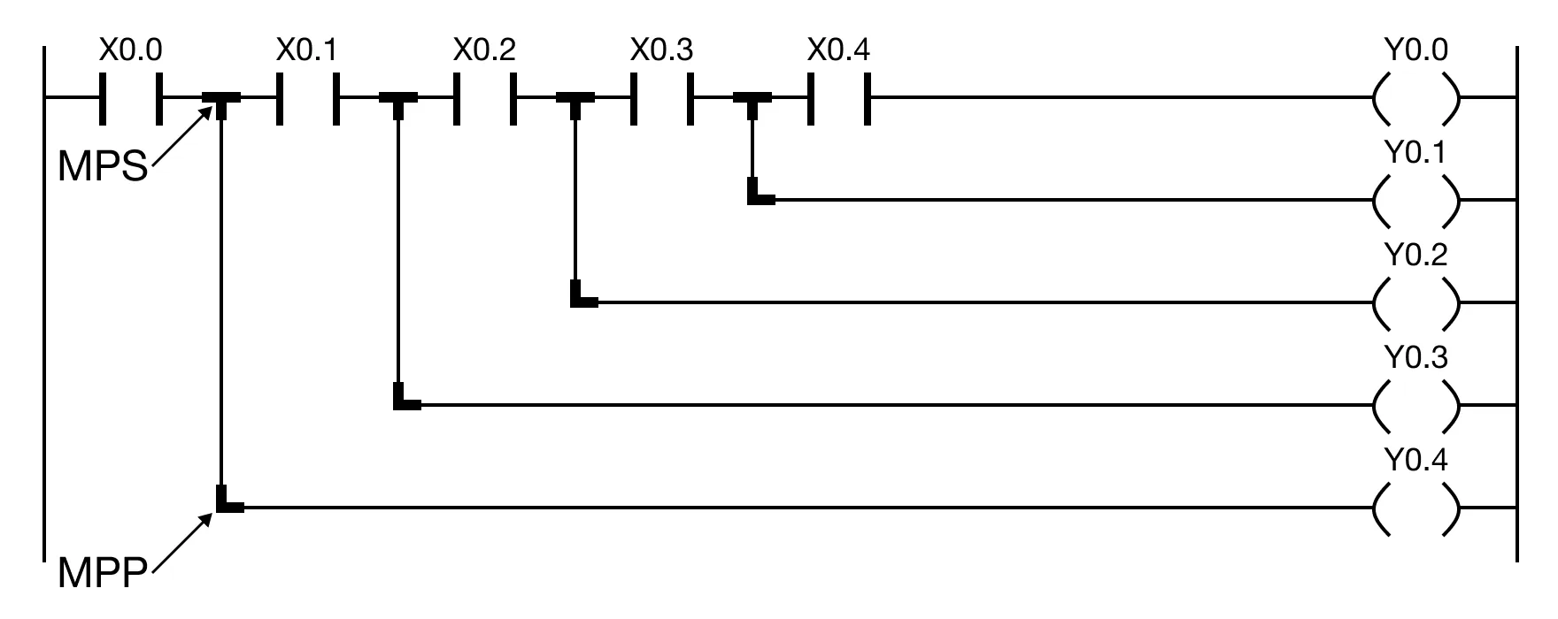
MPS Example 1
The MPS multiple branch connection stores the operation result.

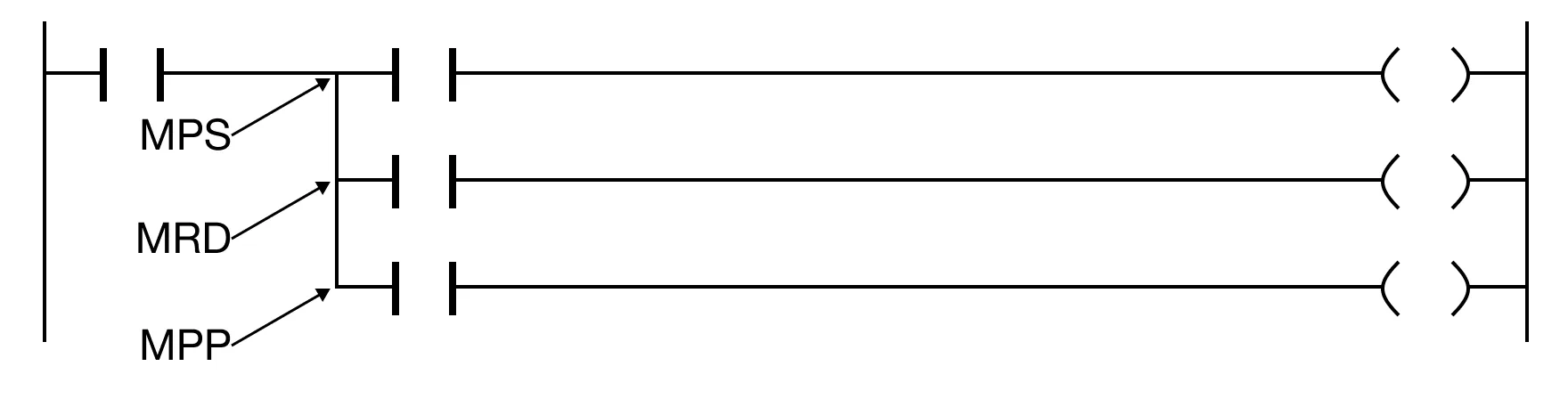
MPS Example 2
The MPS multiple branch connection must be followed by a MPP multiple branch connection.