
Overview & Concepts
EasyDiagnoser is a diagnostic utility included with EasyBuilder Pro that helps monitor communication and system activity within an HMI project. It provides real-time visibility into how the HMI is interacting with connected devices, making it useful for troubleshooting communication issues and verifying that drivers and data exchanges are functioning correctly.
EasyDiagnoser displays runtime diagnostic information generated by the HMI, allowing engineers to observe communication behavior and system messages while the project is running.
Key areas of information provided include:
- Communication polling activity – Shows data exchanges between the HMI and configured devices.
- Device communication status – Indicates whether connected PLCs or devices are responding properly.
- System and macro output messages – Displays runtime messages that can help identify errors or abnormal conditions.
EasyDiagnoser is commonly used during project development, system commissioning, and maintenance. By allowing users to observe communication activity and system responses in real time, it helps identify configuration problems, communication faults, or other operational issues within the HMI project.
Please note that EasyDiagnoser is for Legacy HMI products (HMI5000 Series) only, and not cMT / cMT X Series units. For cMT / cMT X Series diagnostics, please see the cMT Diagnoser feature page.
Implementation
Configuration
Open Utility Manager and click EasyDiagnoser.
Set the HMI IP address. Enter IP address or click [Search All], and then enter [Project Port].


Or, during On-line simulation, right click and select [Run EasyDiagnoser] to open EasyDiagnoser. EasyDiagnoser will monitor the communication between PC and PLC.
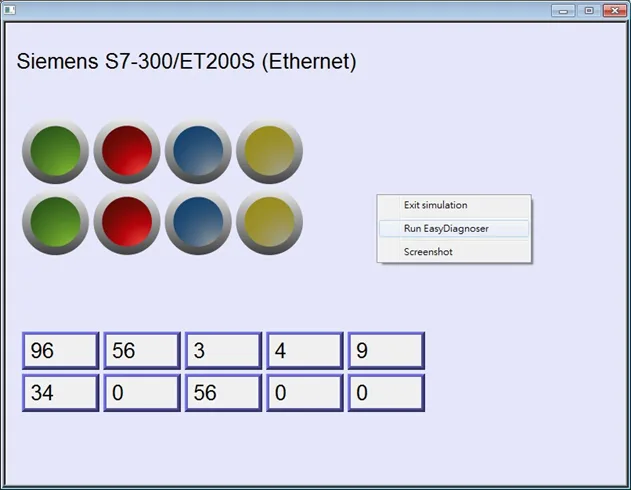
When finished, click [OK], EasyDiagnoser dialog box is shown in the following figure
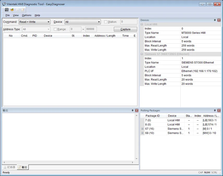
EasyDiagnoser Settings
Main Menu
| Item | Description |
|---|---|
| File | Save As The communication data can be saved as .xls file which can be opened by Excel. Exit Exits current file. |
| View | Device Bar Displays Device window. Package Bar Displays Package window Logger Bar Displays Logger window. Output Bar Displays Output window. |
| Options | Toolbars Displays toolbar icons of Device Bar, Package Bar, Logger Bar, and Output Bar. Status Bar Displays information of CAP, NUM, and SCRL at the bottom of EasyDiagnoser window. Update Package List Displays the Polling Package information of current page. Show Object ID (HMI) Shows the ID of the objects on HMI viewing window. Clear Activity List Clears all the information recorded during communication. |
| Help | Displays EasyDiagnoser version information. |
Activity Area
In the activity area, users can observe the communication between HMI and PLC.
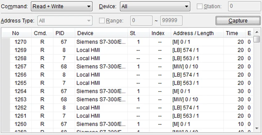
| Item | Description |
|---|---|
| Command | Read + Write Displays Read and Write information in activity area. Read Displays only Read information in activity area. Write Displays only Write information in activity area. |
| Device | All Displays the information of Local HMI and PLC. • If command is set to Read + Write, the Read and Write information of Local HMI and PLC will be displayed in the activity area. • If command is set to Read, the Read information of Local HMI and PLC will be displayed in the activity area. • If command is set to Write, the Write information of Local HMI and PLC will be displayed in the activity area. Local HMI Displays the information of Local HMI. • If command is set to Read + Write, the Read and Write information of Local HMI will be displayed in the activity area. • If command is set to Read, the Read information of Local HMI will be displayed in the activity area. • If command is set to Write, the Write information of Local HMI will be displayed in the activity area. PLC Displays the information of PLC. • If command is set to Read + Write, the Read and Write information of PLC will be displayed in the activity area. • If command is set to Read, the Read information of PLC will be displayed in the activity area. • If command is set to Write, the Write information of PLC will be displayed in the activity area. |
| Station | Selects the PLC station number to be displayed. (This function is disabled when selecting [All] in [Device].) |
| Address Type | Selects all or a preferred address type to be displayed. (This function is disabled when selecting [All] in [Device].) |
| Range | Sets the range of address types. (This function is disabled when selecting [All] in [Device].) |
| Capture | Click to start/stop capturing the communication message. |
Polling Packages
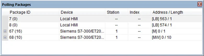
| Item | Description |
|---|---|
| Package ID | Uses the Package ID to check the error of the object. |
| Device | Displays HMI and PLC type. |
| Station | Displays PLC station number. |
| Index | Displays the index register numbers of the objects. |
| Address / Length | Displays the device type and the size of the package (in words). |
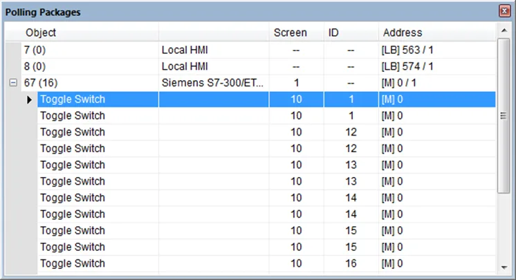
| Item | Description |
|---|---|
| Object | Check the object in the package. |
| Screen | The window in the project where the object is placed. |
| ID | The ID number of the object. |
| Address | The address of the object. |
Notes:
- Click [Package ID], the device station number will be displayed in the 3rd column
![Click [Package ID], the device station number will be displayed in the 3rd column](https://media.maplesystems.com/wp-content/uploads/2026/04/image-419.webp "Station number shows when selecting Package ID")
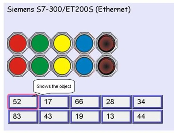
- Double click [Package ID] then select [object] to display the position of the object. For example, select [Numeric Input] and the screen no. displays 10. This shows that this object is in window no. 10 in the project and will be marked with pink frame on HMI as shown in the following figures:
Devices
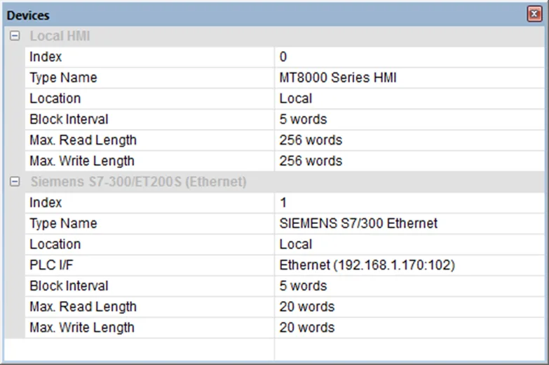
This window displays the information of both the HMI and the PLC or other configured device.
Output (Macro Debug)
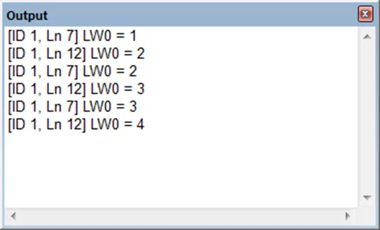
With Macro Trace function, the executing status of Macro can be seen. In the illustration below, for [ID 1, Ln 7] and [ID 1, Ln 12]
ID 1 represents Macro name.
Ln 7 and Ln 12 represent that data are in the 7th and 12th line of Macro.
Error Code Identification and Handling
In the activity area, the reason of error can be found through the error codes listed below:
| Error Code | Cause of Communication Error |
|---|---|
| 0 | Normal |
| 1 | The device is busy and not yet ready to process a command. |
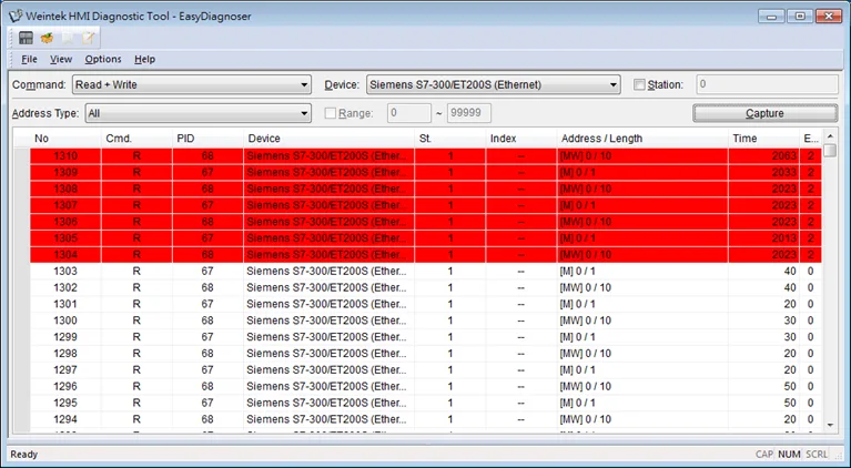
| 2 | Communication error due to unexpected reason. |
| 3 | The device does not exist. |
| 4 | The device using the specified station number does not exist. |
| 5 | Incorrect address format. |
| 6 | Read/Write unsupported address. |
| 7 | The driver of the device does not exist. |
| 8 | The COM port does not exist. |
| 9 | Incorrect IP address or unable to connect the device. |
| 10 | Checksum error. |
| 11 | Unidentified command. |
| 12 | Ignore |
| 20 | The USB device is improperly connected. |
| 21 | The CAN Bus device is improperly connected. |
| 22 | No reply from the device. |
| 23 | Insufficient data read from the device before timeout. |
| 24 | The Conversion Tag used by the object does not exist or the content is incorrect. |
| 25 | HMI is not accepting any commands from a remote HMI. |
| 251 | Read/Write exceeding number of words from/to the register of the MODBUS device. |
| 252 | MODBUS device replies incorrect data format. |
| 253 | MODBUS device checksum error. |
When error occurs, the error message will be shaded red as shown in the following figure:
Window Adjustment
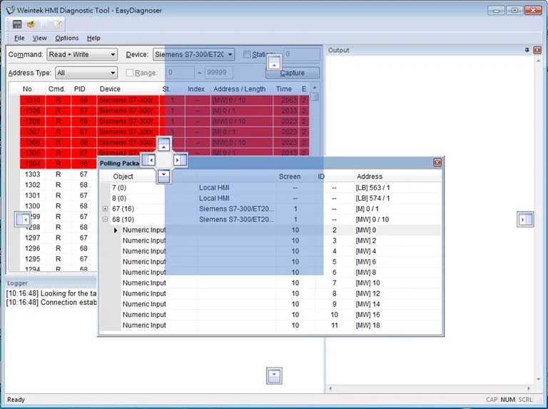
Users can drag or use the smart docking icons in the editing window to place the windows into a different position if desired:
Note:
- EasyDiagnoser does not support Siemens S7/1200 (Ethernet) or Allen-Bradley Ethernet/IP (CompactLogix/ControlLogix) – Free Tag Names drivers due to the tag structure of those drivers.