

Function Key
Overview
The Function Key object can be used for several tasks, such as switching between windows, keypad design, Macro execution, screen hardcopy, and setting USB security key.
Function Keys with [Screen hardcopy] or [Import user data/Use [USB Security Key]] selected do not work remotely on cMT Viewer.
Configuration
Click [Object] » [Function Key] icon on the toolbar to open a Function Key object property dialog box. Set up the properties, press OK button, and a new Function Key object will be created.
General Tab
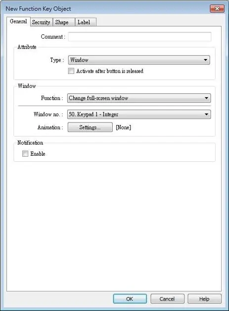
| Setting | Description |
|---|---|
| Activate after button is released | If this function is selected, the action is delayed till button is released; otherwise, the action is executed once the button is pressed. |
| Change window | Change full-screen window: Change to another base window. Change common window: Change common window. Display popup window: A pop-up window displays in the base window. If [Close this popup window when parent window is closed] check box is selected, the pop up window will be closed when change the base window to another window. Otherwise, a function key in the pop up window is needed to close it. (cMT / cMT X Series) Animation Setting: cMT / cMT X Series allows using transition effects for opening popup windows using Function Keys. The settings can be opened by clicking [Animation Setting]. 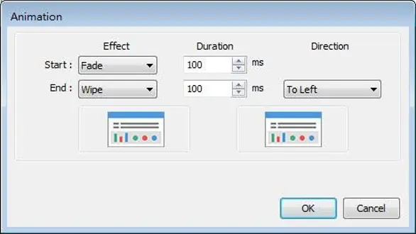 Effects are listed below. Different effects may be used for Start (window appears) and End (window disappears). Effect types: Fade, Fly, Float, Wipe, Split, Circle, Clock, Zoom, Turn, and Push. [Duration] specifies how many milliseconds (ms) a transition effect takes to complete.[Direction] The direction of the transition. Return to previous window: If this is selected, the Function Key will change from the current screen to the previous one displayed. For example, when window no. 10 is changed to window no. 20, press the function key to return to window no. 10. This function is only available for base window. Close window: Close any active pop-up windows, message windows included. Display calculator window (cMT / cMT X Series): If this option is selected, clicking this Function Key can open a calculator with an unchangeable appearance. This calculator allows operators to do simple calculation and enter the result to a destination object by pressing the Enter key. 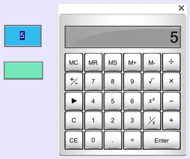 Selecting this option opens [Keep calculation open after paste] checkbox, which keeps the calculator displayed after the value is entered to the object. 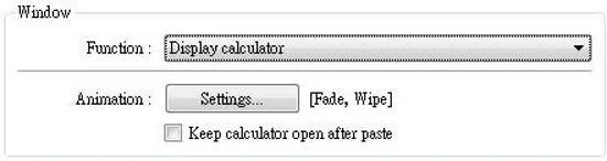 |
| Keyboard Input | Configures the button as a keypad key, and the character it enters, via [Numeric] or [ASCII] objects. Enter: Same as the keyboard’s “Enter” function. Backspace: Same as the keyboard’s “Backspace” function. Clear: Clear the value in the word register. Esc: Same as the [Close window] function; it is used to close the keyboard window. Delete: Same as the keyboard’s “Delete” function, deletes the number or character on the right side of the text cursor. Left: Same as the keyboard’s “←” key moves the text cursor to the left side of the previous number or character. Right: Same as the keyboard’s “→” key moves the text cursor to the left side of the next number or character. Line feed: Move the cursor down to the next line. Inc: Increment by 1. Dec: Decrement by 1. ASCII/UNICODE: Specify the character to be entered by this key. |
| Execute Macro | Select this check box to execute one of the Macros from the drop down list that has already been configured by user. |
| Window title bar | Function Key defined can be used to move a pop-up window which has no [Window title bar] to a preferred position on screen. Select the pop-up window and then click on a preferred position, the window will be moved.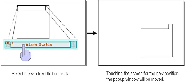 |
| Hard copy screen to USB disk, SD card or printer | Print the current window. Before using this function, choose a printer model in [System Parameter Settings] » [Model] » [Printer]. If a monochrome printer is used, selecting [grayscale] can provide a better print result, but the text may not be clearly printed. To improve text printing, avoid using [grayscale].  Crop window This option can be selected for taking a cropped screenshot. 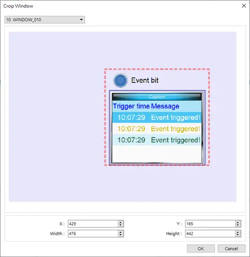 |
| Acknowledge all events (alarms) (cMT / cMT X Series) | Acknowledge all events once by pressing the Function Key. |
| Import user data / Use [USB Security Key] | A Function Key can be used to import the e-mail contacts or user accounts set, also, to log in using USB Security Key.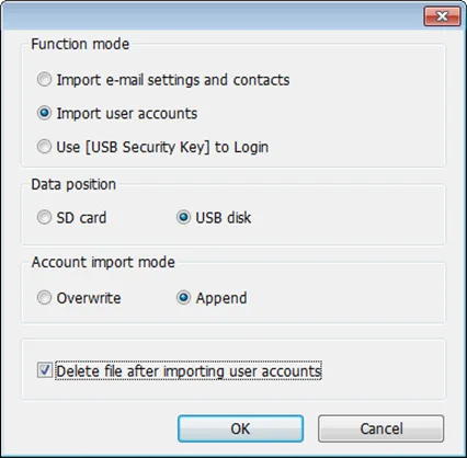 Data Position Select the external device to store data from [SD card] or [USB disk]. Account import mode If [Overwrite] is selected, the existing accounts will be overwritten with new accounts in the external device after importing. If [Append] is selected, HMI will append more accounts while the old accounts still exist.Please note that when [Append] is selected, the accounts that already exist in the project cannot be imported. Delete file after importing user accounts If select this check box, the system will delete the account data saved in the external device after importing, this can prevent the account data from leaking out. |
| Notification | If this selection is enabled, it will notify a designated bit address to set ON or OFF, each time the button is pressed. |
Note:
- [Overwrite] is the only option when importing the e-mail contacts. This means that all existing contacts will be removed first, and then the new contacts are added.

Combo Button
Overview
Combo Button can execute multiple commands. The former way was to overlay multiple objects in the same position, and the commands are executed in the order of the layer of the objects. This takes time to test the order when planning the project. Combo Button allows users to easily set multiple commands with one object, and freely adjust the order of executing commands.
The following are the features of Combo Button:
- Executes multiple commands.
- Allows adjusting the order of executing multiple commands.
- Displays the state in Bit or Word Lamp.
Configuration
Click on the Combo Button icon on the toolbar or select [Objects] » [Combo Button] to create object. Configure object properties, click OK, a new Combo Button object will be created.
General Tab
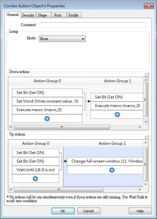
Bit/Word Lamp actions are explained in the Bit Lamp and Word Lamp sections.
For cMT Series, actions can be classified into action groups, which are put in sequence. Actions within a group are executed at the same time, and after the actions in the current group have been all triggered, the actions in the next group will then be triggered. Please see Action Trigger for more information on the notes about action groups.
| Setting | Description |
|---|---|
| Down actions | Execute action when the button is pressed. |
| Up actions | Execute action after the button is pressed and released. |
| Delay | Delay action for the specified time (ms). |
| Set Bit | Sets the designated bit address ON or OFF. Set ON Sets ON the designated bit. Set OFF Sets OFF the designated bit. Toggle Alternates the bit state. Momentary Momentary is a two-step action where pressing the button (Down action) will set the bit ON and then releasing the button (Up action) will set the bit OFF. Corresponding Down and Up actions will be created. |
| Set Word | Changes the value in the designated word address. Write constant value Writes the constant value to the designated register. Increment value (JOG+) Increases value in register by a set amount in [Inc. value], up to the [Upper limit]. Decrement Value (JOG-) Decreases value in register by a set amount in [Dec. value], down to the [Bottom limit]. Dynamic Limits (JOG+, JOG-) Sets the Upper limit (JOG+) and Bottom limit (JOG-) by a designated register. Write constant string Writes the constant string to the designated register. |
| Change window | Switches to the designated window. Change full-screen window: Changes to another base window. Change common window: Changes common window. Return to previous window: Changes from current screen to the previous one displayed. For example, when window no. 10 is changed to window no. 20, this function can be used to return to window no. 10. This function is only available for base window. Animation Setting: The effects are: Fade, Fly, Float, Wipe, Split, Circle, Clock, Zoom, Turn, Push. Different effects may be used for Start (window appears) and End (window disappears). [Duration] specifies how many milliseconds (ms) a transition effect takes to complete.[Direction] The direction of the transition. |
| Execute Macro | Executes one of the Macros from the drop down list that has already been configured by users. In an action group, [Execute Macro] is seen as completed as soon as it is triggered. Even if a particular macro takes longer to complete, the system will not wait for the macro to complete running before moving on to the next action group. |
| Popup Window | Opens a designated window. |
| Close Window | Closes currently opened window. |
| Popup Calculator Window | Opens a calculator with an unchangeable appearance, allowing operators to do simple calculation and enter the result to a destination object by pressing the Enter key. |
| Keyboard Input | Configures the button as a keypad key, and the character it enters, via [Numeric] or [ASCII] objects. Enter: Same as the keyboard’s “Enter” function. Backspace: Same as the keyboard’s “Backspace” function. Clear: Clear the value in the word register. Esc: Same as the [Close window] function; it is used to close the keyboard window. Delete: Same as the keyboard’s “Delete” function, deletes the number or character on the right side of the text cursor. Left: Same as the keyboard’s “←” key moves the text cursor to the left side of the previous number or character. Right: Same as the keyboard’s “→” key moves the text cursor to the left side of the next number or character. Inc: Increment by 1. Dec: Decrement by 1. ASCII/UNICODE: Specify the character to be entered by this key. |
| Screen Hardcopy | Captures the current screen and saves it to an SD card or USB disk. For headless HMI models (cMT-SVR / cMT-SVRX) connected to specified interfaces, the available options for screen hardcopy are as follows: cMT-iV6: The captured screen can be saved to the SD card on cMT-iV6. cMT Viewer on PC: The “Screen Hardcopy” action is not supported, please use the right-click “Screenshot” function instead. cMT Viewer: The “Screen Hardcopy” action is not supported. |
| Acknowledge all events (Alarms) | Acknowledges all events once. |
| Import Data | Imports e-mail contacts or user accounts, or is used as USB Security Key login. Data Position: [SD card] or [USB disk]. Account import mode: If [Overwrite] is selected, the existing accounts will be overwritten by new accounts. If [Append] is selected, accounts are appended. Delete file after importing user accounts: The system will delete the account data saved in the external device after importing; this can prevent the account data from leaking out. |
| Wait Until | The next group will be executed only when the condition set for a designated bit or word address is met. |
| Data Transfer (Global) | Sends the value in the designated address to another address. |
| File Transfer | Transfer files by FTP. HMI will connect to the FTP server in passive mode. General Tab: Download: Transfer file from FTP server to local HMI.Upload: Transfer file from local HMI to FTP server. Server address: [Direct]: Designate server address related settings in EBPro. [Dynamic]: Designate an address for changing the server address related settings dynamically on HMI. Suppose the dynamic address is set to LW-n, then: LW-n: Host usage (0: IP, 1 Domain name) LW-n+1: IP (4 words) LW-n+5: Port LW-n+6: Authentication (0: None, 1: Account) LW-n+7: Username (16 words) LW-n+23: Password (16 words) LW-n+39: Domain name (64 words) Delete the source file after successful transfer Following successful transfer, the source file will be deleted. When transferring in [Download (FTP -> HMI)] mode, please make sure that the account has the write permission on the FTP server. File Tab: Set file position and full path of FTP server / Local HMI. When a folder path is specified, all the files in that folder will be transferred, not including files in subfolders. When a file with identical file name already exists, it will be overwritten regardless. Status Tab: Designate an address for showing file transfer result and FTP server response. Please use the following link for more information on FTP server return codes. |
| Control Token | The action to acquire or unacquire a Control Token. Control Token: Select a Control Token. Action: Set this action to acquire or unacquire a Control Token. Max. waiting time: Continues or stops running the next action group if the Control Token is still not acquired even after the set [Max. waiting time]. |
| Backup | Backup historical data or recipe data to an external storage device, or transfer data via email or FTP server. |
| Safely Remove USB disk/SD card | Safely remove the external storage device to ensure data integrity. |
Note:
- One Combo Button can only do one of these window actions, and only once: [Change Window], [Popup Window], and [Close Window].
- At most 20 groups can be created in a Combo Button, and at most 20 actions can be added into a group.
- File Transfer Error Codes:
| Error Code | Description |
|---|---|
| 0 | File transferred successfully. |
| 1 | The HMI directory for download does not exist. |
| 3 | USB disk or SD card is not found. |
| 4 | HMI or FTP directory is empty. |
| 5 | Uploaded file does not exist. |
| 8 | Operation rejected by FTP server. |
| 9 | USB disk or SD card is full. |
| 10 | Unknown error. |

Bar Graph
Overview
Bar Graph object displays data as a bar graph for visualization.
Configuration
Click [Object] » [Chart] » [Bar Graph] icon on the toolbar to open Bar Graph dialog box. Select properties, click OK button, a new Bar Graph object is created.
General Tab
| Setting | Description |
|---|---|
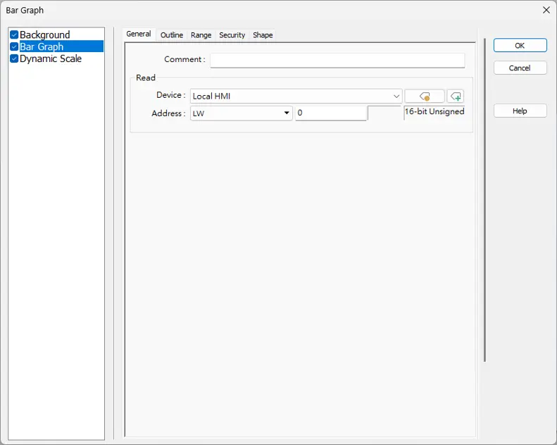
| Read address | Click [Setting] to Select the [Device], [Device type], [Address], [System tag], and [Index register] of the word devices that controls how the bar graph displays. |
Outline Tab
| Setting | Description |
|---|---|
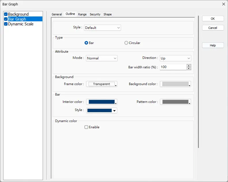
| Type | Choose either [Bar] or [Circular]. |
| Attribute | Mode Choose either [Normal] or [Offset]. If [Offset] is selected, an original value [Origin] must be entered for reference. Direction / Degree Bar: Determine the bar graph direction. Available options are [Up], [Down], [Right], and [Left]. Circular: Determine the circular bar graph direction. Available options are [Clockwise] and [Counter clockwise]. 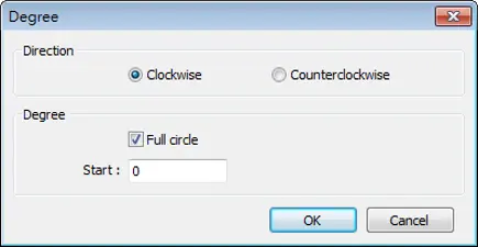 If [Full circle] is selected, set the start degree. If [Full circle] is not selected, set the start and end degree. Bar width ratio (%) The ratio of bar to object width. The figure below shows two ratios, 100% and 50%. 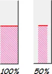 Hole Radius (%) The ratio of the radius of the hole to the radius of the whole circular bar graph. The figure below shows two ratios, 0% and 50%. 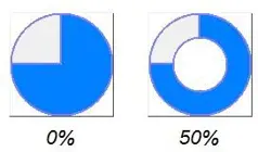 |
| Color/Style | Set the bar’s frame and background color, bar style, and bar color. 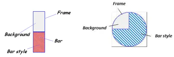 |
| Dynamic color | (For cMT / cMT X Series models only) With this option selected, the interior color of the bar is determined by the value in the designated address.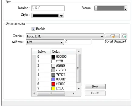 |
Range Tab
| Setting | Description |
|---|---|
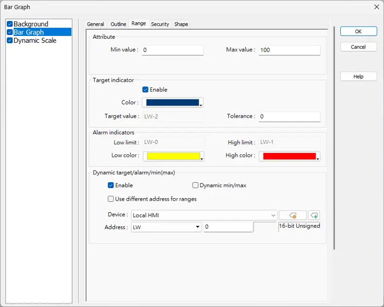
| Min value / Max value | The percentage of filling can be calculated by the formula, see Example 1. |
| Target indicator | When the register value meets the condition, the color of filled area will change to the target color, see Example 2. |
| Alarm indicators | If the register value is larger than [High limit], the color of filled area will change to [High color]. If the register value is smaller than [Low limit], the color will change to [Low color]. Please note that when [Dynamic color] is enabled, the Target indicator and Alarm indicator settings will not be present and their colors are determined by the designated addresses. |
| Dynamic target/alarm/min(max) | When enabled, the [Low limit] and [High limit] of [Alarm indicators] and the [Target Value] of [Target indicator] will use designated registers, which is shown in their respective fields, see Example 3. When [Dynamic min/max] is enabled, the [Min value] and [Max value] of [Attribute] will use designated registers, which is shown in their respective fields. When [Use different address for ranges] is enabled, the addresses mentioned above can be configured independently and read from different registers. This option is only supported on cMT / cMT X. |
Examples:
Example 1: Min/Max Values
The percentage of filling in a Bar Graph can be calculated using the following formulas:

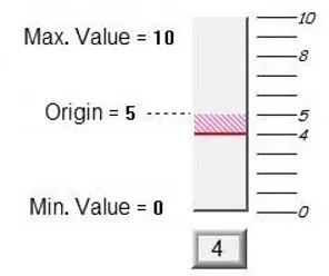
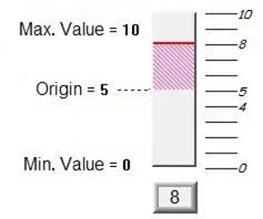
Assume [Offset] is selected. If (Register value – [Origin]) is greater than 0, the bar will fill upwards from the [Origin]. If (Register value – [Origin]) is less than 0, the bar will fill downwards from the [Origin].
The following diagrams demonstrate the filling behavior of the Bar Graph when the origin is set to 5, the max. value is 10, and the min. value is 0, using different data sets.
If the value at read address is 4:
If the value at read address is 8:
Example 2: Target Indicator
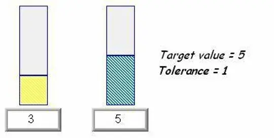
When the register value meets the following condition, the color of filled area will change to the target color.
[Target Value] – [Tolerance] ≤ Register value ≤ [Target Value] + [Tolerance]
Assume [Target Value] is 5 and [Tolerance] is 1. As shown below, if the register value is equal to or larger than 4 (=5-1) and equal to or less than 6 (=5+1), the filled area’s color of the bar will change to the target color.
Example 3: Dynamic Addresses
The high and low limits for alarm indicators can be set by designated registers. When the write address is LW-n, the limits and related setting addresses will be automatically determined based on the following rules (assuming [Dynamic min/max] is enabled).
| Data Format | 16-bit | 32-bit | 64-bit (cMT / cMT X only) |
|---|---|---|---|
| Low Limit | LW-n | LW-n | LW-n |
| High Limit | LW-n+1 | LW-n+2 | LW-n+4 |
| Target Value | LW-n+2 | LW-n+4 | LW-n+8 |
| Min Value | LW-n+3 | LW-n+6 | LW-n+12 |
| Max Value | LW-n+4 | LW-n+8 | LW-n+16 |
| Origin | LW-n+5 | LW-n+10 | LW-n+20 |
Combo Setting: Background and Dynamic Scale
cMT / cMT X Series HMI support combo setting for Bar Graph, which allows setting of multiple related objects at a time. Bar Graph can be set with Background and Dynamic Scale.
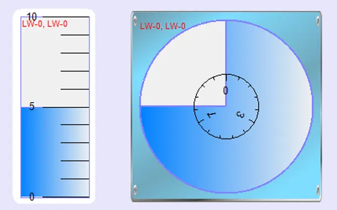
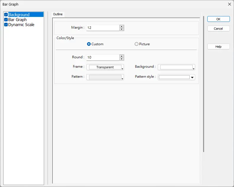
Background
| Setting | Description |
|---|---|
| Margin | Specify the space between the background edge and the objects. |
| Color/Style | Customize Select a suitable background pattern and color. 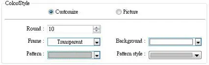 Picture Use the default picture or choose a picture from Picture Library. 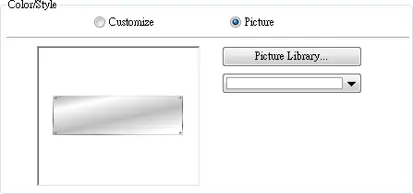 |
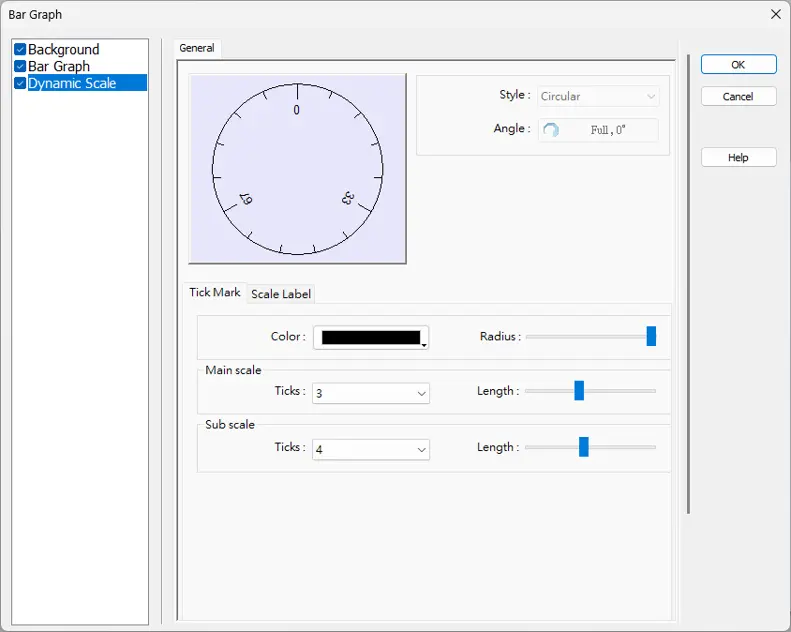
Dynamic Scale
| Setting | Description |
|---|---|
| Style | The scale style will follow the bar type. |
| Tick Mark | Configure the number of tick marks for main and sub scales. If the style is circular, the radius and tick mark length can be specified. |
| Scale Label | Configure the font, font color, font size and other attributes of scale label. |

Meter Display
Overview
Meter Display object displays the value of word register with a meter.
Configuration
Click [Object] » [Chart] » [Meter Display] icon on the toolbar to open the Meter Display dialog box. Set the object’s attributes and then click OK to create a new Meter Display object.
General Tab
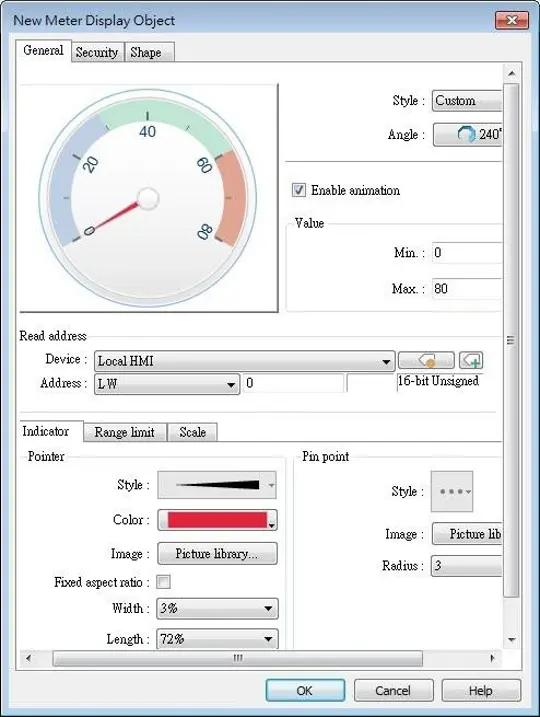
| Setting | Description |
|---|---|
| Style | Select a style from the drop-down list. Available options include: [Custom], [Style 1], [Style 2], and [Classical]. If [Custom] is selected, properties such as the width / length of the pointer or the radius of the pin point, etc must also be manually set. The following background-related settings are available using [Style 1], [Style 2], or [Classical]: Color Sets the color of the background picture of meter. Outline The following is the outline of Style 1 when [Full circle], [Half circle], or [Quarter circle] is selected. ![The following is the outline of Style 1 when [Full circle], [Half circle], or [Quarter circle] is selected.](https://media.maplesystems.com/wp-content/uploads/2026/06/meter-outline.webp) The following is the outline of Style 2 when [Full circle], [Half circle], or [Quarter circle] is selected. ![Image of the outline of Style 2 when [Full circle], [Half circle], or [Quarter circle] is selected.](https://media.maplesystems.com/wp-content/uploads/2026/06/meter-outline-2.webp) Rotation Rotates the background picture clockwise according to the angles set. |
| Angle | Direction Sets the range to label the scale, using twelve o’clock direction as the 0° reference. Degree Available options include: [Predefined] and [Custom]. With [Predefined] selected, pick from the thumbnails configure directions and angle ranges with ease. 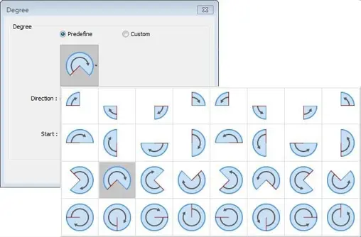 Full circle If selected, the full circle is drawn according to the selected direction and the start angle. The limits are determined by the value set in [Minimum] and [Maximum] field under [Value]. |
| Enable animation | If selected, the pointer slides to the designated position when the read value changes; if not selected, the pointer directly points to the designated position when the read value changes. |
| Value | Sets the lower and upper limits of the meter. |
| Read address | Displays the value in meter according to the value in the designated word register. |
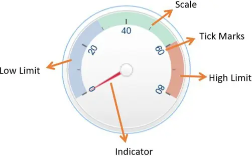
| Indicator | Sets the style of pointer and pin point. If [Custom] is selected, the direction of the pointer must points upward to correctly display. |
| Range limit | Sets the values for low and high limits and the colors for alert indications. Dynamic limits The low and high limits are determined by specified registers. See Example 2 below. If the option to use different addresses is selected, the limits can be configured to read from different registers. |
| Scale | Sets the number of main and sub scale, the color of tick marks and scale label. |
Examples:
Example 1: Pointer Position Calculation
Set object’s display range. Meter Display object will use the value of [Zero] and [Span] and the value of register to calculate the pointer’s position. For example, supposed that [Zero] is 0, [Span] is 100, when the value of register is 30, [Start degree] is 0, and [End degree] is 360, then the degree indicated by the pointer is:
![Meter Display object will use the value of [Zero] and [Span] and the value of register to calculate the pointer’s position](https://media.maplesystems.com/wp-content/uploads/2026/06/deg-formula.webp "Illustration of the pointer position calculation formula")
Pointer will be pointing at 108 degrees.
Example 2: Dynamic Limits
The low limit and high limit are set by the register.
Suppose the address is LW-n, the following table shows the read address of low limit and high limit:
| Content | 16-bit | 32-bit | 64-bit (cMT / cMT X only) |
|---|---|---|---|
| Low limit | LW-n | LW-n | LW-n |
| High limit | LW-n+1 | LW-n+2 | LW-n+4 |
So, when address is LW-100, the rule of setting limits is:
| Content | 16-bit | 32-bit | 64-bit (cMT / cMT X only) |
|---|---|---|---|
| Low limit | LW-100 | LW-100 | LW-100 |
| High limit | LW-101 | LW-102 | LW-104 |