

Multi State Switch
Overview
Multi-state Switch object is a combination of Word Lamp object and Set Word object. The appearance of the object is controlled by the value of the read word address. As well, pressing the button sets the value in the word address according to the settings.
Configuration
Click [Object] » [Multi-State Switch] icon on the toolbar to open a Multi-State Switch object property dialog box. Set up the properties, press OK button, and a new Multi-State Switch object will be created.
General Tab
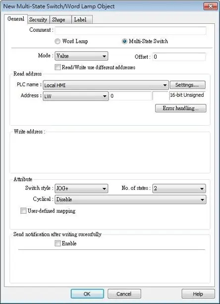
| Setting | Description |
|---|---|
| Comment | User can describe the information of the object. Word Lamp / Multi-State Switch Switch between Word Lamp and Multi-State Switch features. |
| Model / Offset | Different modes can be selected: [Value], [LSB]. For more information, see the Word Lamp page. |
| Read/Write use different addresses | Different addresses can be used to read data and write data. |
| Read address | Click [Setting] to select the [PLC name], [Address], [Device type], [System tag], [Index register] of the word device that controls the Multi-state Switch object. Users can also set address in [General] tab while adding a new object. When [Read/Write use different addresses] option is not selected, the title of this group box will be “Read/Write address”. |
| Write address | Click [Setting] to select the [PLC name], [Address], [Device type], [System tag], [Index register] of the word device that controls the Multi-state Switch object. Users can also set address in [General] tab while adding a new object. Write after button is released If this function is selected, the action is delayed till button is released; otherwise, the action is executed once the button is pressed. |
| Attribute | Switch style Select the object’s operation mode, see Example 1. User-defined mapping The value placed in the write register of each selection, the action taken when an illegal value is entered, and error notification to a designated bit address can be set. 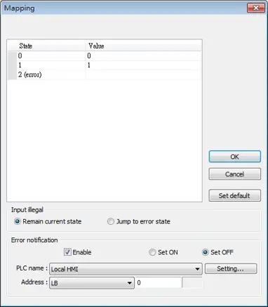 Remain current state If an illegal value is entered, Multi-state Switch will remain at the current state. Jump to error state If an illegal value is entered, Multi-state Switch will jump to the error state. Error notification If an illegal value is entered, automatically set the value placed in the designated register. |
| Send notification after writing successfully | After the system successfully writes data to PLC, the designated bit address will be set On/Off. |
| Error handling (cMT / cMT X Series) | The action taken when an illegal value is entered or notify a designated bit address. This is similar to [User-defined mapping]; the difference is the value corresponding to each state need not to be preset. |
Examples:
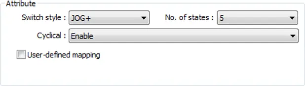
JOG +
Increase the value of a designated register by 1 each time when pressing the button, till the value equals to [No. of states]. A cyclic action can be enabled. As shown below, each time when pressing the button, the state number will add 1 start from state 0, till state 4 ([no. of state]-1), and returns to 0 and step up again.
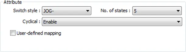
JOG –
Decrease the value of the designated register by 1 each time when pressing the button, till the value equals to 0. A cyclic action can be enabled. As shown below, each time when pressing the button, the state number will minus 1 start from state 4 ([no. of state]-1), till state 0, and returns to state 4 and step down again.

Numeric
Overview
Numeric object can be used to input or display the value of a designated word register.
Configuration
Click [Object] » [Numeric] icon on the toolbar to open a Numeric object property dialog box. Set up the properties, press OK button, and a new Numeric object will be created.
General Tab
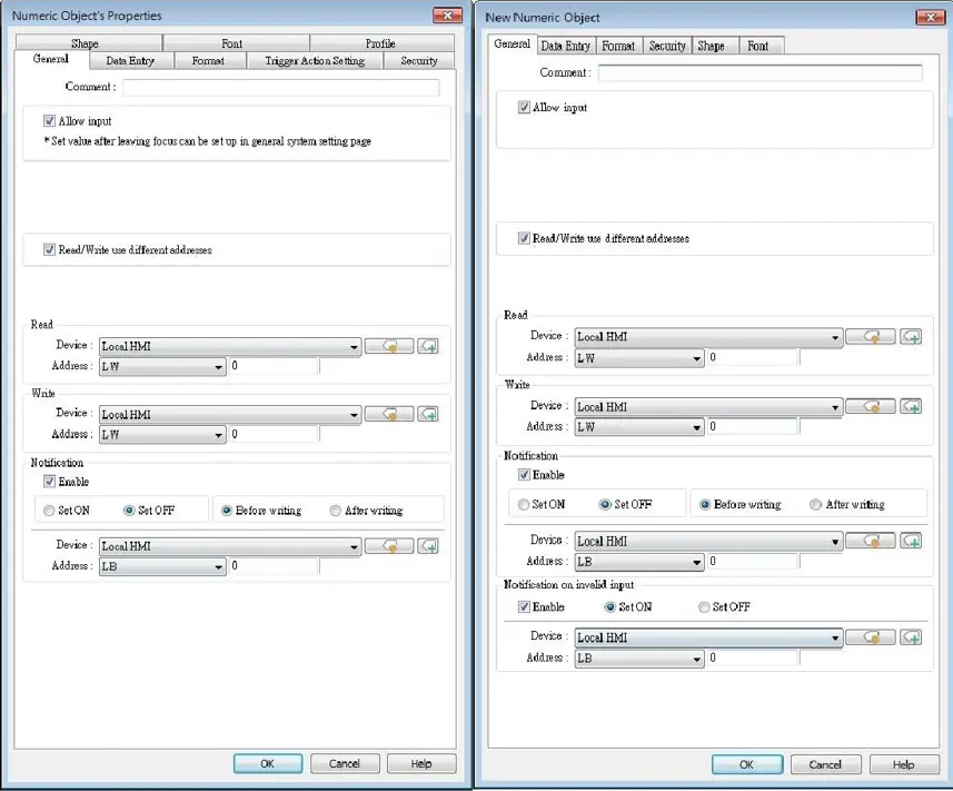
| Setting | Description |
|---|---|
| Allow input | If selected, the input features and relevant settings are enabled. |
| Read / Write use different addresses | Different addresses can be used to read data and write data. |
| Read address | Click [Setting] to select the [Device], [Address], [Device type], [System tag], [Index register] of the word device that displays the value. Users can also select a tag defined in Address Tag Library. When [Read/Write use different addresses] option is not selected, the title of this group box will be “Read/Write address”. |
| Write address | Select the [Device], [Device type], [Address] of the word device that system writes to. |
| Notification | With notification enabled, the state of the designated bit address can be set on / off, before / after writing. Notification works differently comparing cMT / cMT X Series with Legacy Series. cMT/cMT X Series: Trigger the object to open a keyboard window » Notification before writing » Enter a value and press ENTER » Start writing operation » Notification after writing. Legacy Series: Trigger the object to open a keyboard window » Enter a value and press ENTER » Notification before writing » Start writing operation » Notification after writing. |
| Notification on invalid input | If an illegal value is entered, automatically set the state of a designated register. |
Data Entry Tab
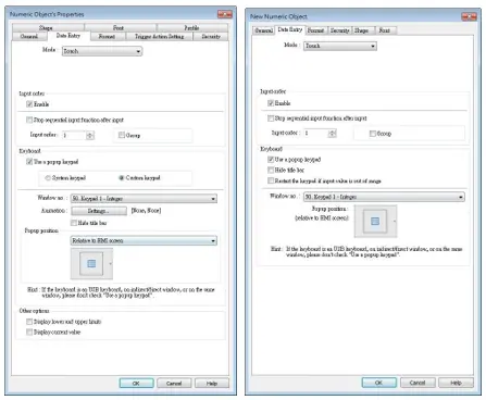
| Setting | Description |
|---|---|
| Mode | Touch Used when data entry is initiated by touching the screen object. Bit control Used when data entry is enabled by turning ON a designated bit, and entry ends when the bit goes OFF. |
| Input control | Specify a bit address that enables or ends data entry. The order of data entry is specified in [Input order] and an external USB keyboard is needed for data entry. For cMT-SVR, use cMT Viewer’s keyboard. |
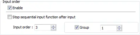
| Input order | Perform continuous input by setting [Input order] and [Group]. The criterion of searching the next input object: • The range of [Input order]: 1 ~ 511, range of [Group]: 1 ~ 15. • If [Group] is not selected, its input order is 0. • The system only searches for the objects within the same Group. • The lower number of order is entered before the higher number of order. • For multiple objects within the same group and with the same input order, the object placed in the lower layer is entered first. |
| Keyboard | Use a popup keypad If selected: A pre-designed pop-up keypad can be chosen by selecting a check box and selecting the relative position on the HMI screen. When data entry is enabled, the pop-up keypad displays in the selected position, and closes when data entry ends. If not selected: When data entry is enabled, the pop-up keypad is not displayed. Users may: • Create a custom design on the same screen window. • Use a USB keyboard. System keypad cMT / cMT X Series model has its own system keypad, select this checkbox to use the system keypad, or select [Custom keypad] to set up a customized keypad. Animation Setting When using a cMT / cMT X Series model with [Custom keypad] selected, the transition effect of the keypad window can be selected. Hide title bar Use a keypad without the title bar. Popup position When using a cMT / cMT X Series model with [Custom keypad] selected, the position where the keypad pops up can be selected. The position can either be relative to HMI screen or relative to object. Restart the keypad if input value is out of range When entering data, if the value entered is not within the valid range, the system will automatically restart the keypad. |
| Other options (For cMT / cMT X Series) | Display lower and upper limits If selected, when entering a value, the range is displayed near the object. Display previous value If selected, when entering a value, the value before update is displayed near the object. |
Example:
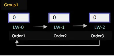
This example demonstrates how to use [Input Order] and [Group] to perform continuous input in several Numeric objects. After entering data in one object, entry will be passed to the next input order object which is in the same group.
Create three Numeric objects, and set [Input order] to 1, 2, and 3 respectively. Include the three objects in [Group 1] as shown in the following figures:
LW-0
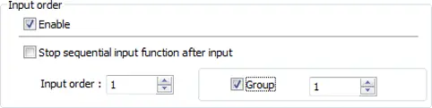
LW-1
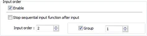
LW-2
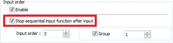
When finish entering data in the last object, to end data entry of all objects, please select [Stop sequential input function after input] check box:
Format Tab
| Setting | Description |
|---|---|
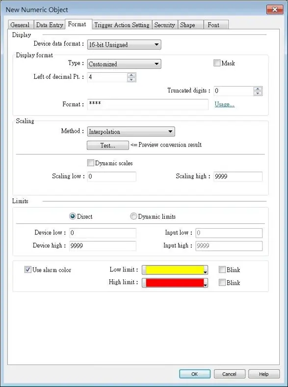
| Device Data Format | Set the data format of a designated word register. Options include: BCD, Binary, Unsigned, Signed, HEX, and Float. 16-bit uses 1 word where 32-bit uses two words. Mask If selected, any values entered will be hidden by displaying them as asterisks “*”. |
| Display format | Default General Numeric formats. Customized Each “#” sign represents each integer digit, and each “#” sign represents each fraction digit that will be displayed in the Numeric object. Float and Double formats are only supported on cMT / cMT X models. Apart from “#” signs, extra texts can be entered in the [Format] field, for example: kg. The available alignment options are: [Left], [Center], [Right], [Leading zero]. The numeric value represented by “#” sign will be displayed from the highest digit to the lowest in the Numeric object. Truncated digits Specify the number of digits to be truncated, from the lowest digit to the highest. The number of “#” signs = [Left of decimal Pt.] – [Truncated digits] – [Right of decimal Pt.]. The number of “#” signs = [Right of decimal Pt.] – [Truncated digits]. 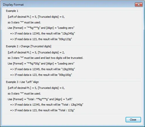 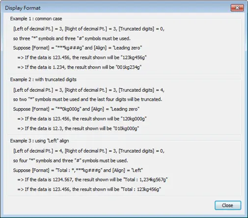 When leading zero is not used, the text enclosed in two “#” signs will not show. Scientific Notation (cMT / cMT X Series) Express numerical data using scientific notation; for example, number 100 is displayed as 1e+2. Scientific notation is not available for device data formats: BCD, HEX, or Binary. |
| Number of digits | Left of decimal Pt. The number of digits before the decimal point. Right of decimal Pt. The number of digits after the decimal point. |
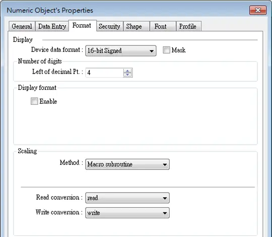
| Scaling | Interpolation If this check box is selected, [Engineering low] and [Engineering high] boxes appear. Values entered in these boxes correspond to the display range required. The setting also requires [Input low] and [Input high] in the limits section. See Example 2. Test: Preview the result of Interpolation. See Example 2. Dynamic scales: Set the [Engineering low] and [Engineering high] by a designated register. See Example 4. Macro subroutine The value read from or written to the register can be computed by macro subroutines selected in [Read conversion] and [Write conversion]. The macro subroutines should be defined in Macro Function Library. |
| Limits | This section enables users to apply display limits to the values in the input register and set the display color to be used when the register value falls outside the specified limits. Direct Set the limits by entering values in [Device low] and [Device high]. If the value entered is outside the limits, the value in the register cannot be changed. Dynamic limits Set the limits by specifying a register. To use consecutive addresses, see Example 5. On a cMT / cMT X model with the [Use different addresses] option selected, it is possible to set the high and low limits by specifying different addresses. If the scaling method used is interpolation, both high and low limit addresses are required. |
| Use alarm color | Low limit When the value in the register is outside the [Low limit], the object displays digits by using the set color. High limit When the value in the register is outside the [High limit], the object displays digits by using the set color. Blink When the value in the register is outside either limit, the digits flash. |
Trigger Action Setting Tab (cMT / cMT X Series)
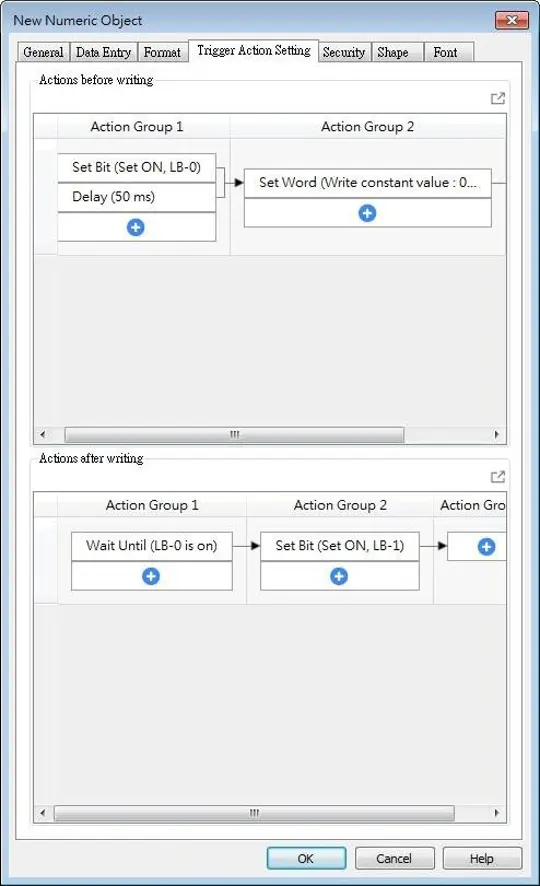
Actions executed before/after writing can be classified into action groups. The groups are put in sequence. The actions within the same group are executed at the same time. When all the actions within the same group are completed, the actions in the next group are then executed.
Compared to the Notification actions selected in General tab, Trigger Action Setting offers more flexible combination of actions. For more details about these settings, please also see Action Trigger object page.
| Setting | Description |
|---|---|
| Actions before writing | The predefined action groups will be executed once the write operation starts, and will not wait for it to be completed. |
| Actions after writing | The predefined action groups will be executed when the write operation is completed. |
Example 1: Rules of using macro subroutine
- There must be a return value and exactly one parameter.
- Examples:
- sub char test (short a) // (Correct)
- sub test (char a) // (Incorrect, no return value.)
- sub char test (char a, char b) // (Incorrect, two parameters.)
- Examples:
- Use the Macro data type that corresponds to the object’s data format; the mapping is per the below table.
- Examples:
- sub char test(unsigned short a) // (Correct)
- sub char test(char a) // (Incorrect)
- Examples:
| Macro Data Type | Numeric Object Data Format |
|---|---|
| short | 16-bit Signed |
| Int | 32-bit Signed |
| unsigned short | 16-bit BCD, 16-bit HEX, 16-bit Binary, 16-bit Unsigned |
| unsigned int | 32-bit BCD, 32-bit HEX, 32-bit Binary, 32-bit Unsigned |
| float | 32-bit Float |
| long | 64-bit Signed (cMT / cMT X only) |
| unsigned long | 64-bit Unsigned (cMT / cMT X only) |
| double | 64-bit Double (cMT / cMT X only) |
- Supports only the local HMI address.
- Examples:
- GetData(var, “Local HMI”, LB, 0, 1) // (Correct)
- GetData(var, “MODBUS RTU”, 0x, 0, 1) // (Incorrect)
- Examples:
- The following system defined functions are unable to be invoked:
- ASYNC_TRIG_MACRO, SYNC_TRIG_MACRO, DELAY, FindDataSamplingDate, FindDataSamplingIndex, FindEventLogDate, FindEventLogIndex, INPORT, INPORT2, OUTPORT, PURGE, TRACE
- The following statements are not supported:
- For-Next, While-Wend
Example 2: Interpolation
If [Interpolation] is selected, the scaling equation is as the following: If A indicates the original data and B indicates the displayed data:
B = [Engineering low] + (A – [PLC low]) × Ratio
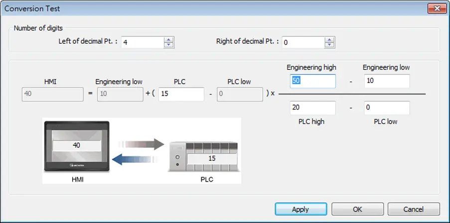
where, Ratio = ([Engineering high] – [Engineering low]) / ([PLC high] – [PLC low]) As shown below, the original data is 15, after conversion, 40 will be displayed.
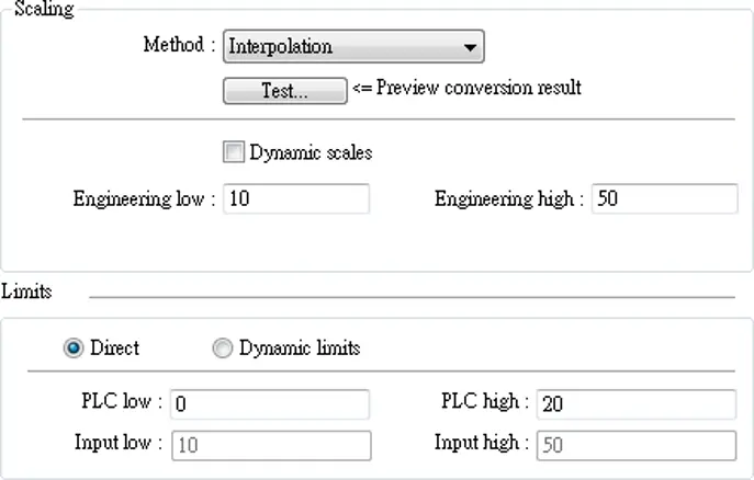
Click [Test] button to preview the result of Interpolation. Enter a value in [PLC] field as shown in the following figure, for example, enter value 15, and the result, which is 40, will be displayed.
Example 3: Decimal Adjustment
If the numeric format selected is not Float and decimal point is used, the decimal place of the converted result will not be adjusted automatically, please adjust [Engineering high] to correctly place the decimal point of the result gained in [Interpolation] mode. Please see the illustration below.
Create two Numeric objects, set [Right of decimal Pt.] to 1 and select [Interpolation] method for one of the objects as shown in the following figure.
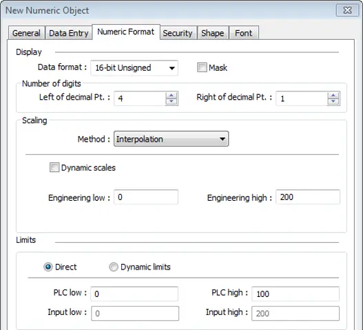
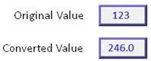
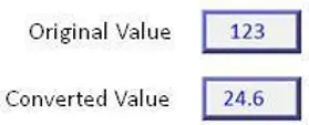
When you enter value “123”, the object set to [Interpolation] displays “246.0” instead of “24.6”.
To move the decimal point one place to the left, adjust [Engineering high] as shown in the following figure.
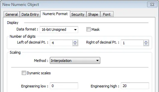
Now, when entering 123, the converted value is 24.6
Example 4: Dynamic Limits: Engineering Low/High
If [Interpolation] is selected, set the [Engineering low] and [Engineering high] by a designated register. When Dynamic Address is LW-n, where n is an arbitrary number, the rule of setting [Engineering low] and [Engineering high] is:
| Content | 16-bit | 32-bit | 64-bit (cMT / cMT X only) |
|---|---|---|---|
| Dynamic address | LW-n | LW-n | LW-n |
| Engineering low | LW-n | LW-n | LW-n |
| Engineering high | LW-n+1 | LW-n+2 | LW-n+4 |
So when the address is LW-100, the rule of settings limits is:
| Content | 16-bit | 32-bit | 64-bit (cMT / cMT X only) |
|---|---|---|---|
| Dynamic address | LW-100 | LW-100 | LW-100 |
| Engineering low | LW-100 | LW-100 | LW-100 |
| Engineering high | LW-101 | LW-102 | LW-104 |
Example 5: Dynamic Limits via Designated Registers
Set the limits by a designated register. When [Address] is LW-n and [Use consecutive addresses] is selected, the rule of setting limits is:
| Content | 16-bit | 32-bit | 64-bit (cMT / cMT X only) |
|---|---|---|---|
| Address | LW-n | LW-n | LW-n |
| Low limit | LW-n | LW-n | LW-n |
| High limit | LW-n+1 | LW-n+2 | LW-n+4 |
So when the address is LW-100, the rule of settings limits is:
| Content | 16-bit | 32-bit | 64-bit (cMT / cMT X only) |
|---|---|---|---|
| Address | LW-100 | LW-100 | LW-100 |
| Low limit | LW-100 | LW-100 | LW-100 |
| High limit | LW-101 | LW-102 | LW-104 |
Example 6: Use Macro subroutine for scaling
The following demonstrates how to use [Macro subroutine] for scaling when configuring Numeric object.
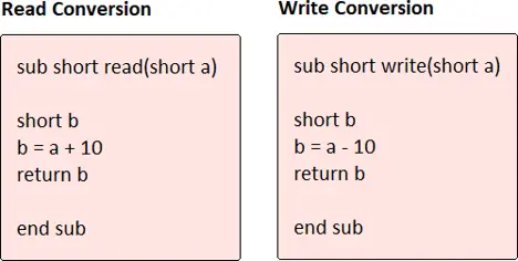
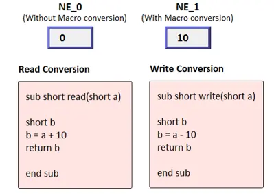
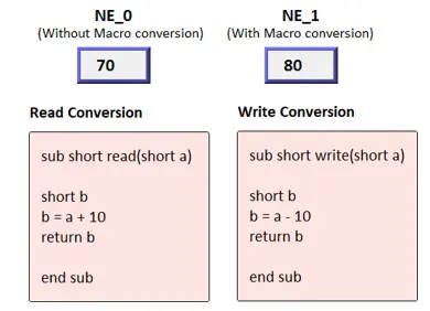
The following two macros are used, one for [Read conversion] and one for [Write conversion].
Create two Numeric objects: NE_0 and NE_1 and use the same control address. Select [Macro subroutine] for NE_1.
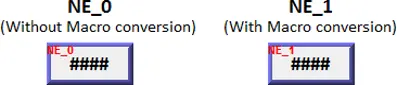
Enter 0 in NE_0 then NE_1 will execute [Read conversion]. The value gained will be 10.
Enter 80 in NE_1, [Write conversion] is executed and the value gained will be 70. NE_0 displays 70.
Note:
- If executing [Read conversion] and [Write conversion] by the same numeric object, the value entered in this object is computed by the Macro subroutine of [Write conversion] first, and then the result is computed by the Macro subroutine of [Read conversion]. In Example, if the subroutine of [Write conversion] is set to b=a-20, then entering 80 in NE_1 will get 60 after [Write conversion] and then the object displays 70 after [Read conversion].
Security Tab
| Setting | Description |
|---|---|
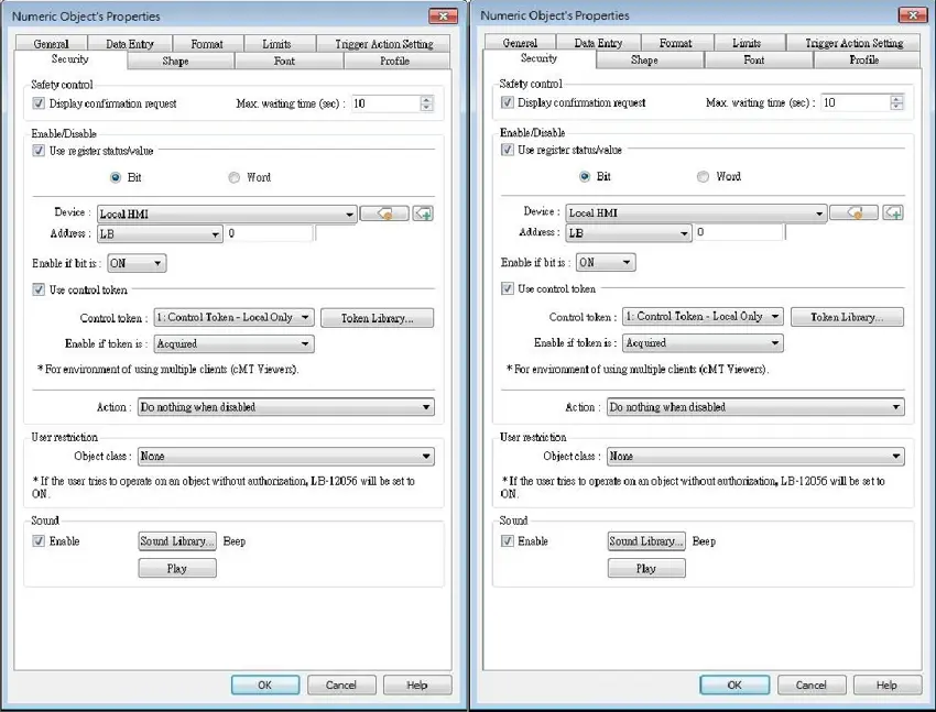
| Safety control | Displays a confirmation request window before executing a command. |
| Enable/Disable | Use register status / value With this option selected, whether an object is operable depends on whether the specified condition occurs in the designated address. Use control token With this option selected, whether an object is operable depends on whether a control token is acquired or unacquired. Action modes: Do nothing when disabled The object is not operable, and its status remains unchanged when the specified condition does not occur in the designated address. Hide when disabled The object is hidden when the specified condition does not occur in the designated address. Grayed label when disabled The value in the object turns gray when the specified condition does not occur in the designated address. |
| User restriction | Set the security class of the object to be operated by an authorized user. |
| Sound | When enabled, the selected sound will be played when the object is touched. |
Font Tab
| Setting | Description |
|---|---|
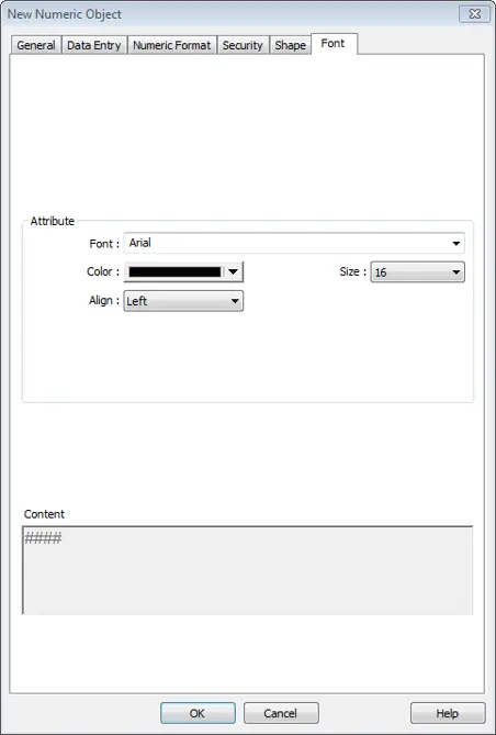
| Color | When the value is within the limits, display digits using color set in this tab. |
| Align | Left: Align the number to the left. Center: Align the number to the center. Right: Align the number to the right. Leading zero: The number is preceded with leading zeros when the number of digits is less than that set. 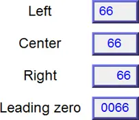 |
| Size | Set the font size. |

ASCII
Overview
ASCII object can be used to input or display ASCII or UNICODE characters held in designated word registers.
Configuration
Click [Object] » [ASCII] icon on the toolbar to open an ASCII object property dialog box. Set up the properties, press OK button, and a new ASCII object will be created.
General Tab
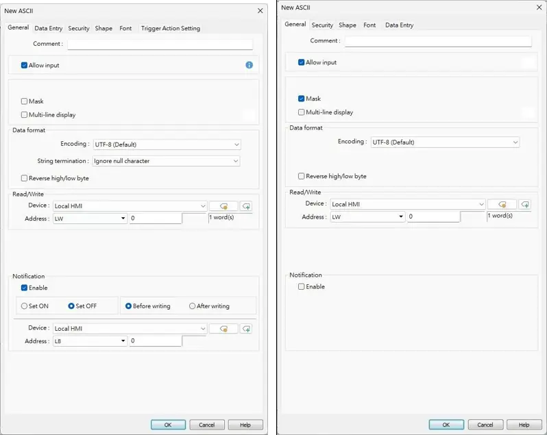
| Setting | Description |
|---|---|
| Allow input | If selected, the input features and relevant settings are enabled. |
| Mask | If selected, any values entered will be masked by asterisks (*). |
| Multi-line display | If selected, the ASCII object can display multi-lined text. If a line feed character LF (0xA) is used in the string, a new line will be created. |
| Vertical alignment | When [Multi-line display] is enabled, the method to vertically align multiple lines of text can be selected. |
| Encoding | Select encoding from UTF-8 (default), Unicode, or Latin-1. |
| String termination | Ignore null character, or treat the first encountered \0 as the end of the string. |
| Reverse high/low byte | Normally an ASCII code is displayed in “high byte”, “low byte” order. Reverse selection makes the system display ASCII characters in “low byte”, “high byte” order.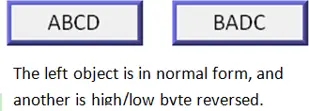 |
| Read address | Click [Setting] to select the [PLC name], [Address], [Device type], [System tag], [Index register] of the word device that displays characters. Users can select a defined address tag from Address Tag Library, or set address in [General] tab while adding a new object. No. of words Select the maximum number of words to be displayed. cMT / cMT X Series: max. 160 words Legacy HMI Series: max. 64 words |
| Notification | With notification enabled, the state of the designated bit address can be set on / off, before / after writing.Notification works differently comparing cMT/cMT X Series with eMT/iE/XE/mTV Series. cMT/cMT X Series: Trigger the object to open a keyboard window » Notification before writing » Enter a value and press ENTER » Start writing operation » Notification after writing. Legacy HMI Series: Trigger the object to open a keyboard window » Enter a value and press ENTER » Notification before writing » Start writing operation » Notification after writing. |
Note:
- A UNICODE character uses 1 word, and an ASCII character uses 1 byte. Therefore 1 word can be used as 1 UNICODE character or 2 ASCII characters. (1 word equals to 2 bytes)
Font Tab
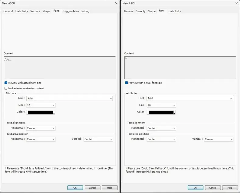
| Setting | Description |
|---|---|
| Preview with actual font size | Preview in the Content field based on the font and size settings specified in the Attribute. |
| Lock minimum size to content | If selected, the ASCII object’s width automatically adjusts to the minimum width necessary to display all the text. |
| Attribute | The font, size, color, and alignment can be set. |
| Text Alignment | Multiline text is aligned within the label outline. The method to align multiple lines of text can be selected. |
| Text area position | Multiline text is aligned within the object outline. The label outline is highlighted by red dotted line and the object outline is highlighted by blue dotted line. Please note that this feature is ineffective when [Multi-line display] is enabled in General tab. |
Trigger Action Setting Tab (cMT / cMT X Series)
Actions executed before/after writing can be classified into action groups. The groups are put in sequence. The actions within the same group are executed at the same time. When all the actions within the same group are completed, the actions in the next group are then executed.
Compared to the Notification actions selected in General tab, Trigger Action Setting offers more flexible combination of actions. For more details about these settings, please also see Action Trigger object page.
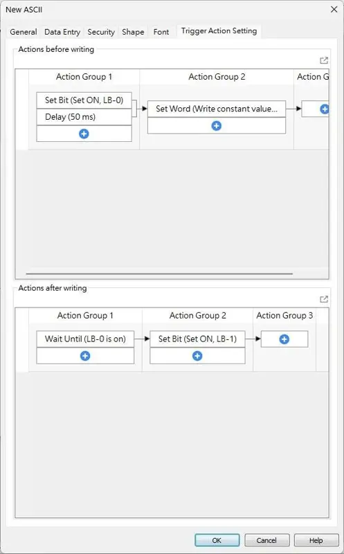
| Setting | Description |
|---|---|
| Actions before writing | The predefined action groups will be executed once the write operation starts, and will not wait for it to be completed. |
| Actions after writing | The predefined action groups will be executed when the write operation is completed. |

Slider
Overview
Slider object is used to change the value in a designated word register address by moving the slide on the screen.
Configuration
Click [Object] » [Slider] icon on the toolbar to open a Slider object property dialog box. Set up the properties, press OK button, and a new Slider object will be created.
General Tab
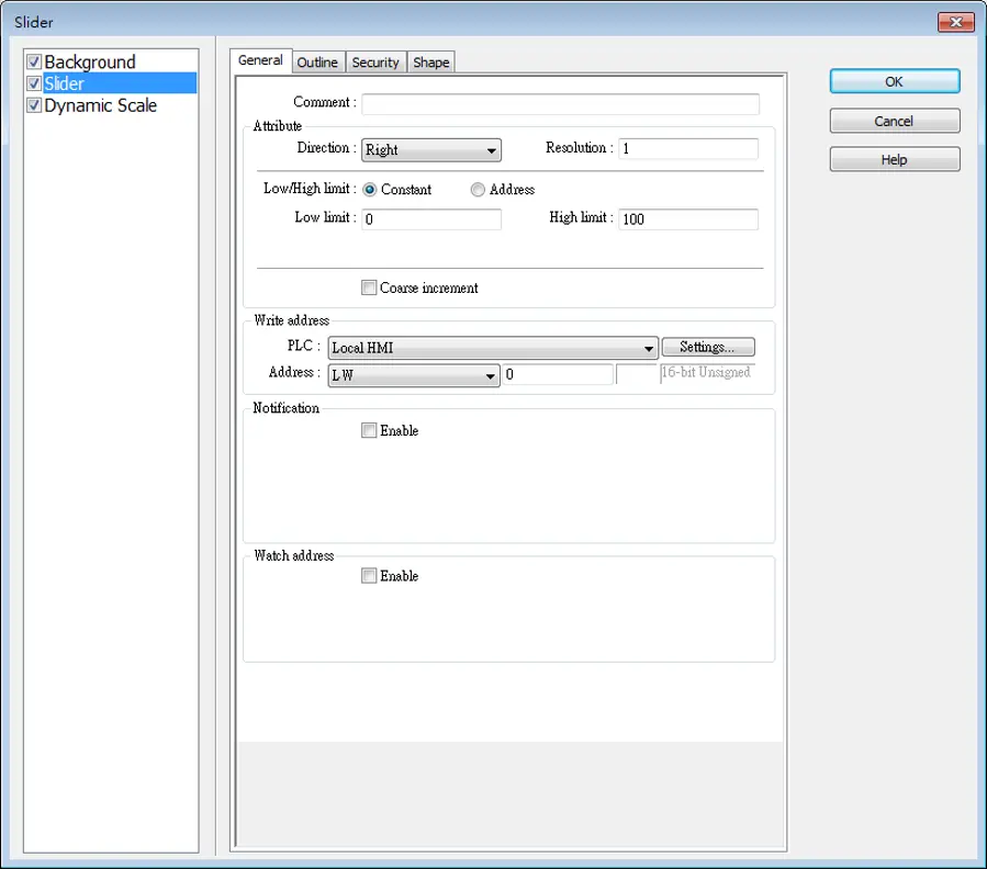
| Setting | Description |
|---|---|
| Attribute | Direction Select the direction of the slider. (Right, Up, Left, Down) 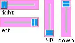 Resolution Sets the value change in the word register for each step of the Slider. For example, if set to 10, the register value changes by 10 points for each increment or decrement on the Slider. Constant Sets the range of the Slider. For example, If set [Low limit] to 5, and [High limit] to 100, the Slider will enter values between 5 and 100. Address Set the [Low/High limit] by a designated register, see Example 1. Coarse increment Apart from moving the roller to change the value as in [Resolution], if this option is selected, the word value will increase / decrease by the [Increment] value each time the object is touched. |
| Write address | Click [Setting] to select the [Device], [Address], [Device type], [System tag], [Index register] of the word device that controls the Slider object. Users can also set address in [General] tab while adding a new object. |
| Notification | If enabled, the state of a designated bit address will be set to ON or OFF before or after writing. Click [Setting] to select the [Device], [Address], [Device type], [System tag], [Index register] of the bit device that controls the notification settings. Users can also set address in [General] tab while adding a new object. [Before writing] / [After writing] Change the state of a designated bit register before, or after the slider is slid. |
| Watch address | When moving the roller, the new value written to the word register address can be displayed in real time. |
Example:
Set the low or high limit by a designated register. When write address is LW-n, where n is an arbitrary number, the rule of setting limits is:
| Content | 16-bit | 32-bit | 64-bit (cMT / cMT X only) |
|---|---|---|---|
| Address | LW-n | LW-n | LW-n |
| Low limit | LW-n | LW-n | LW-n |
| High limit | LW-n+1 | LW-n+2 | LW-n+4 |
So, when address is LW-100, the rule of setting limits is:
| Content | 16-bit | 32-bit | 64-bit (cMT / cMT X only) |
|---|---|---|---|
| Address | LW-100 | LW-100 | LW-100 |
| Low limit | LW-100 | LW-100 | LW-100 |
| High limit | LW-101 | LW-102 | LW-104 |
Outline Tab
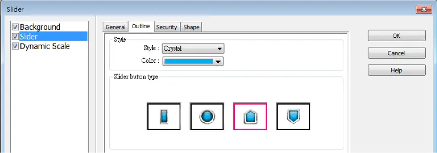
| Setting | Description |
|---|---|
| Slider button type (cMT / cMT X) | Select slider button type, by default, a picture selected from the Picture Library can be the slider button. |
| Slider button type (eMT, iE, XE, mTV) | Four default styles are offered, and the width and color of the Frame, Background, and Slot can be set.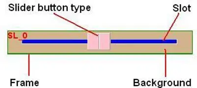 |
Slider Combo Setting (cMT / cMT X Series)
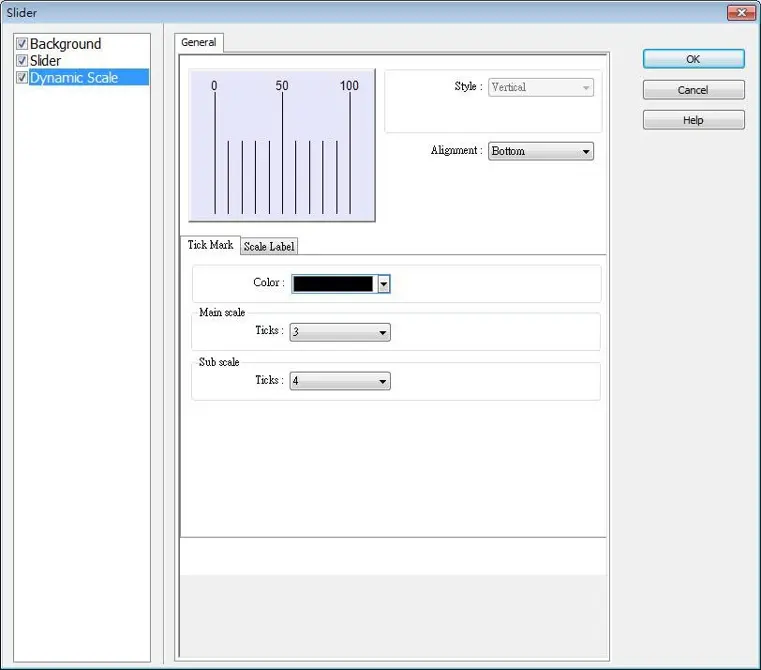
cMT / cMT X Series HMI support combo setting for Slider, which allows setting of multiple related objects at a time. Slider can be set with Background and Dynamic Scale.
Background
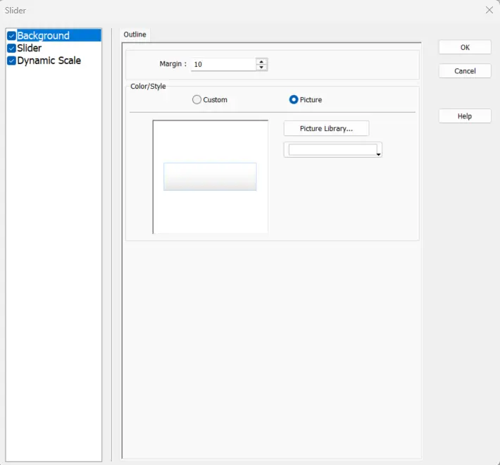
| Setting | Description |
|---|---|
| Margin | Specify the space between the background edge and the objects. |
| Color/Style | Customize Select a suitable background pattern and color. 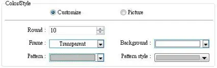 Picture Use the default picture or choose a picture from Picture Library. 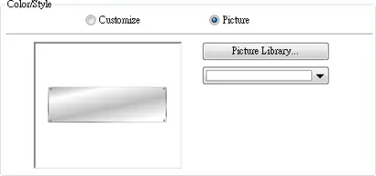 |
Dynamic Scale
| Setting | Description |
|---|---|
| Style | The scale style will follow the Slider. |
| Alignment | The position of the scale bar along the Slider. |
| Tick Mark | Configure the number of tick marks for main and sub scales, and the color of tick marks. |
| Scale Label | Configure the font, font color, font size and other attributes of scale label. In Slider settings if [Address] is selected for Low/High limit, then Scale Label’s [Dynamic limits] will be set automatically. In Slider settings if [Left] is selected for Direction, then Scale Label’s [Reverse (Left/Right)] will be set automatically. 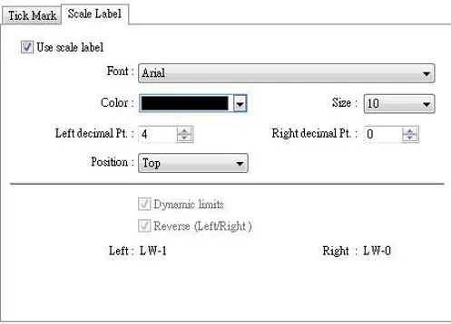 |