
Overview & Concepts
The Data Block Display object in EasyBuilder Pro is used to display groups of register values in a structured table format on the HMI screen. Instead of showing individual register values one at a time, the object allows multiple sequential registers to be viewed together as a block of data. This makes it easier for operators or engineers to monitor related values within a single display.
The Data Block Display is configured by defining a starting register address and the number of values to display. The object then reads a continuous range of registers from the specified device and presents them in rows and columns. This structure allows large datasets to be viewed in a compact and organized way.
Typical uses of Data Block Display include:
- Viewing sequential PLC registers such as D registers or memory blocks
- Monitoring groups of process variables that are stored in consecutive addresses
- Displaying arrays or datasets used in calculations, recipes, or system monitoring
Because it works with sequential register ranges, the Data Block Display is particularly useful for systems where multiple related values are stored together in memory. It provides a convenient way to observe these values without creating individual display objects for each register.

Implementation
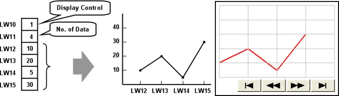
Click the [Object] » [Chart] » [Data Block Display] icon on the toolbar to open the property dialog box. Set up the properties, press OK button, and a new Data Block Display object will be created.
General Tab
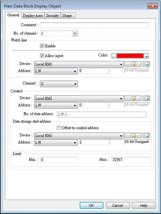
| Setting | Description |
|---|---|
| Comment | Description of the object. |
| No. of channel | Set the no of channel for this object. Each channel represents one data block. The maximal number of channels is 12. |
| Watch Line | If enabled, when user touches the [Data Block Display] object, it will display a vertical cursor line on it, and store the data on the line to the designated registers. See Example 1. Allow input (cMT / cMT X Series)With this checkbox selected, entering a value in the specified address for watch line can move the vertical watch line to the desired position. |
| Channel | Select the channel to be configured. |
| Control address | Specify the control address also the data source. Control address is used to control and clear the drawn curve. After executing the operation below, the system will reset the control word to zero. Enter “0” = No action (default) Enter “1” = Draw (Without clear first) Enter “2” = ClearEnter “3” = Redraw No. of data address If control address is LW-n, then LW-n+1 stores the number of word devices in each data block, i.e. the number of data. The maximum value is 1024. Data storage start address If [Offset to start address] is enabled, the [Offset value storage address] will be set as [Control address] + 2.If select 16-bit data format, the address for each data will be start address, start address + 1, start address + 2 and so on.If select 32-bit data format, the address for each data will be start address, start address + 2, start address + 4 and so on. For more information about control address, see Example 2 to 5. |
| Limit | Set the minimum and maximum limit for the curve. |
Note:
- Without clearing the drawn lines, Data Block Display can be drawn a number of times by entering value 1 in the control address repeatedly. The way to calculate the maximum number of times is: 32 divided by the number of channels.
- 1 channel –> 32 times
- 2 channels –> 16 times
- 16 channels –> 2 times
Examples
Example 1: How to use the Watch Function
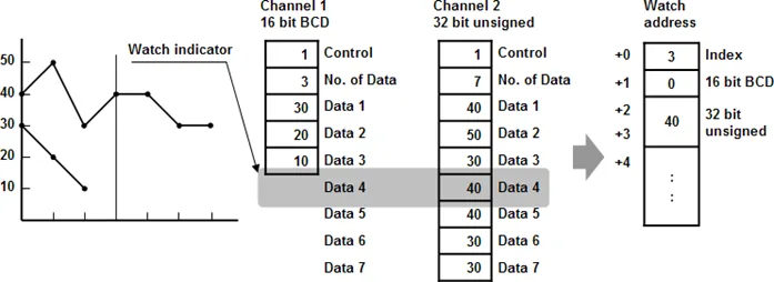
Use “Watch” function to check the value of any point of the curve. When the user touches
[Data Block] object, it will display a “cursor line”, and the system will write the index and value
of that data on the cursor line to the designated address.
| Data Format | Index Value | Channel 1 Value | Channel 2 Value |
|---|---|---|---|
| 16-bit | Address | Address + 1 | Address + 2 |
| 32-bit | Address | Address + 2 | Address + 4 |
| 64-bit (cMT/ cMT X only) | Address | Address + 4 | Address + 8 |
When watch address is set to LW-n, the value written into LW-n represents the channel index
number to be called up. (Start from 0)
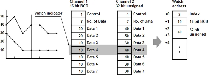
Notes:
- [Data Index] is a 16 bit unsigned integer. When the designated register of cursor line is 32 bit device, it will be stored in the bit 0-15.
- If the channel to be viewed has no data, “0” will be displayed, as shown below. In the example, there is no data in channel 1, when the cursor points at Data 4, “0” will be displayed as shown below.
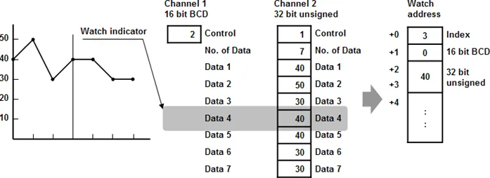
- If there is less data in Channel 1, “0” will be displayed, as shown below.
Example 2: How to show a data block
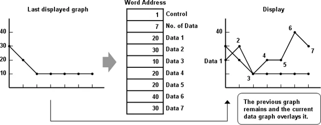
- Write the number of data to [No. of data address], i.e. “Control address+1”
- Store the data consecutively beginning at [Data storage start address].
- Write “1” to [Control address] to draw the curve without cleaning the plot. All previous curves will not be erased.
- The system will write “0” to [Control address] after marking the plot.
Note:
- Do not change the content of [Control address], [No. of data address] and [Data storage start address] between step 3 and step 4 above; doing so might cause errors for the trend curve plot.
Example 3: How to clear the graph
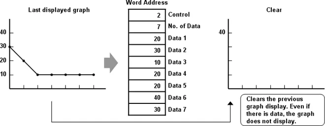
- Write “2” to [Control address], all the trend curves will be cleared.
- The system will write “0” to [Control address] after the trend curve is cleared.
Example 4: How to clear the previous trend curve and display a new one
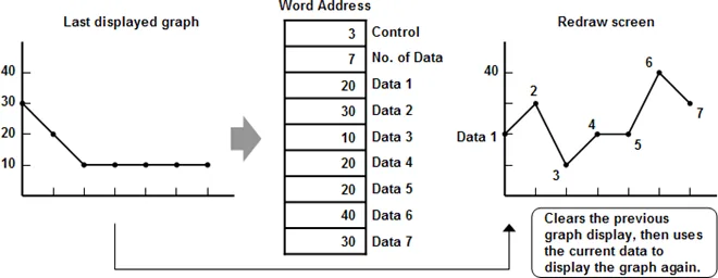
- Write the number of data to [No. of data address], i.e. “control address+1”
- Store the data consecutively beginning at [Data storage start address].
- Write “3” to [Control address], the previous trend curves will be cleared and the new content in data block will be plotted on the screen.
- The system will write “0” to [Control address] after the trend curve has been plotted.
Example 5: Using Offset Mode
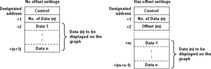
If [Offset to start address] is selected, [Control address], [No. of data address], and [Offset value storage address] will use 3 consecutive addresses.
For example, assume the total number of channels is 3 (start from 0 to 2), and the [Control address] are LW-0, LW-100, and LW-200, respectively. Then, the other addresses will be set as follows: (In the example, format 16-bit Unsigned is used and [Offset value storage address] are all m).
| Item | Channel 0 | Channel 1 | Channel 2 |
|---|---|---|---|
| Control Address | LW-0 | LW-100 | LW-200 |
| No. of data address | LW-1 | LW-101 | LW-201 |
| Offset value storage address | LW-2 (=m) | LW-102 (=m) | LW-202 (=m) |
| Data 1 | LW-0+m | LW-100+m | LW-200+m |
| Data 2 | LW-1+m | LW-101+m | LW-201+m |
| … | … | … | … |
The following figure on the left shows the result when offset mode is not used while the figure on the right shows the result when offset mode is used.
Notes:
- When [Control address] is set to LW-n, [No. of data address] and [Offset value storage address] are as follows:
| Data Type | 16-bit | 32-bit | 64-bit (cMT / cMT X only) |
|---|---|---|---|
| Control address | LW-n | LW-n | LW-n |
| No. of data address | LW-n+1 | LW-n+2 | LW-n+4 |
| Offset value storage address | LW-n+2 | LW-n+4 | LW-n+8 |
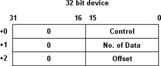
- If the control registers are 32-bit devices, only bit 0-15 will be used for control purpose, bit 16-31 will be ignored. (as illustrated below)
- When the value in [Control address] is not zero, the system will read [No. on data address] and [Offset value storage address].
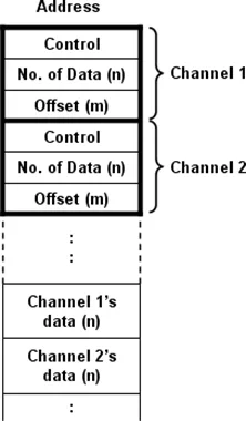
- It is recommended to use [Offset to start address] for data block display with multiple channels and the same device type. As shown in the following figure, The control words of channel 1 is located from LW-n, the control words of channel 2 is located from LW-n+3, and so on.
Display Area Tab
| Setting | Description |
|---|---|
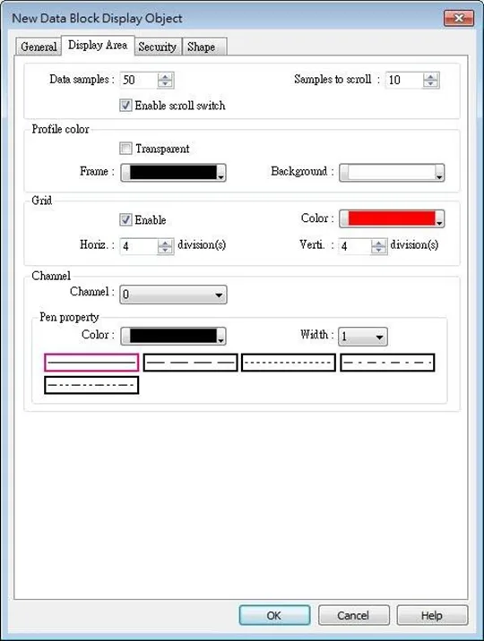
| Description | Data samples Configure the maximal number of data samples (points) to be displayed. Samples to scroll Configure the number of data samples being scrolled. Enable scroll switch Clicking the double arrow icons displays the previous or next data point. Clicking single arrow icons displays the first or the last data point. |
| Profile | Set the color of the frame and background of the object. Transparent Hides the background. Color selection will not be available. |
| Grid | Set the number of horizontal and vertical divisions shown by grid. |
| Channel | Set the color, width and style of each curve. |