
Overview & Concepts
Barcode Scanner operation in EasyBuilder Pro allows an HMI to receive and process barcode data from an external scanner. When a barcode is scanned, the scanner sends the encoded data to the HMI, which can then store the value in a register and use it within the project. This allows scanned information such as product IDs, serial numbers, or work order numbers to be incorporated into system operations.
Barcode scanners typically communicate with the HMI through supported interfaces such as serial communication ports or USB connections. Once connected, the scanner sends the barcode data as a string that the HMI reads and stores in designated registers.
Typical barcode scanner applications include:
- Reading product or batch identification codes
- Entering serial numbers or tracking information automatically
- Selecting recipes or production parameters based on scanned codes
By capturing barcode data directly into the HMI, the system can reduce manual input, improve accuracy, and streamline data entry for production or tracking operations.
Implementation
Barcode Scanners, both Serial and USB, are entered as devices within EasyBuilder Pro. This is done in the Device tab of the System Parameters Menu.
Connecting a Barcode Scanner
In EasyBuilder Pro click [System Parameters] » [Device list] and add a new device.
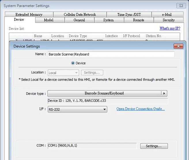
Click [I/F] to select serial interface or USB option, depending on the specifics of your barcode scanner.
Click [Settings…] and finish the settings. This is where you configure the serial port settings.
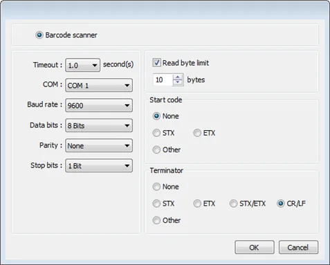
| Setting | Description |
|---|---|
| Timeout | When [Barcode scanner] is selected, if the device reads slowly, a longer timeout is suggested for the device to complete reading data. When [Keyboard] is selected, a time range can be set for keyboard entries. The system starts counting time from the first entry. |
| COM Baud rate Data bits Parity Stop bits | When using COM port, please set the communication parameters correctly. When using USB, there is no need to set the parameters. |
| Read byte limit | With this option selected, the number of bytes a barcode scanner reads is restricted in order to prevent overloading. The range is 10 to 1024. Please note that the data cannot be read if it exceeds the limit. |
| Start code | The data is only valid when the first data is identical to the start code, otherwise the data will be ignored. The start code will not be stored in the address of barcode scanner. None When no start code is used, HMI will save all the data to the designated address of barcode scanner. STX Use 0x02 as start code. ETX Use 0x03 as start code. Other Use user-defined start code. Example: If the start code is 255 (0xff), and the data read is: 0xff 0x34 0x39 0x31 0x32 0x30 0x30 0x34 0x37 The data saved in the designated barcode scanner address will be: 0x34 0x39 0x31 0x32 0x30 0x30 0x34 0x37 |
| Terminator | A terminator represents the end of data stream. None When no terminator is used, HMI will save all the data to the designated address of barcode scanner. STX Use 0x02 as terminator. ETX Use 0x03 as terminator. STX/ETX Use 0x02 or 0x03 as terminator. CR/LF Use 0x0a or 0x0d as terminator. Other Use user-defined terminator. Example: If the terminator is 55 (0x37), and the data read is: 0x34 0x39 0x31 0x32 0x30 0x30 0x34 0x37 The data saved in the designated barcode scanner address will be: 0x34 0x39 0x31 0x32 0x30 0x30 0x34 |
After adding the barcode scanner in the device list, it can then be selected in object settings with the following addresses to use.
| Address Type | Address Name | Description |
|---|---|---|
| Bit | FLAG | FLAG 0 indicates the status of data reading. When reading data, the status of FLAG 0 is set OFF and will return ON after reading data successfully. |
| Bit | RESET | RESET 0 clears the data of BARCODE and RESULT when set ON. |
| Bit | CONNECT_STATUS | CONNECT_STATUS 0 indicates whether the barcode scanner (USB interface) is connected. When the status is ON, the barcode scanner is connected. |
| Word | BARCODE | BARCODE 0: Number of bytes currently read. BARCODE 1 ~ n: Stores the data read. |
| Word | RESULT | RESULT 0 indicates the result of data reading. The following codes indicate: 0x00 Waiting to read BARCODE. 0x01 BARCODE successfully read. 0x02 Invalid BARCODE format. 0x03 The number of bytes specified in [Read byte limit] exceeded. 0x04 The Start Code of the data read does not match the setting. 0x05 The Terminator of the data read does not match the setting. |
Example
The following is a setting example, the barcode is 9421007480830. BARCODE 0 is the address of Numeric Object (BYTES) and BARCODE 1 ~ n is the address of ASCII object (BARCODE).
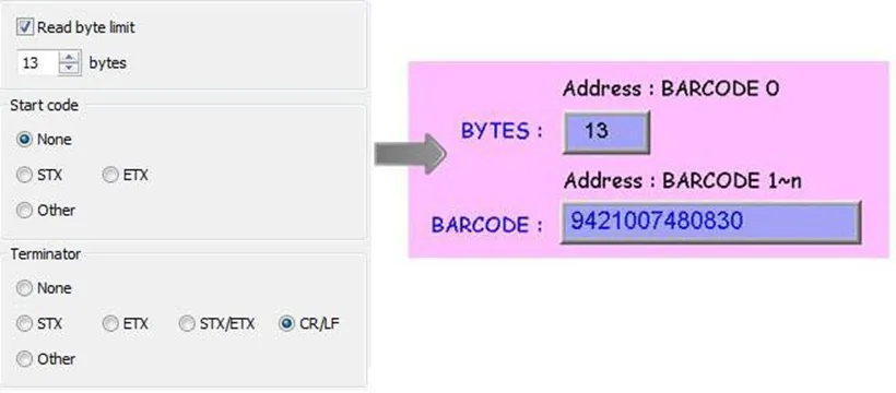
In the example the data stored in the barcode scanner address is listed in the following table:
| Barcode Scanner Address | Data |
|---|---|
| BARCODE 0 | 13 bytes (decimal) However, the data saved is 14 bytes = 7 words. It is because when the number of bytes is an odd number, the system adds a byte (0x00) to make it an even number. |
| BARCODE 1 | 3439 (HEX) |
| BARCODE 2 | 3132 (HEX) |
| BARCODE 3 | 3030 (HEX) |
| BARCODE 4 | 3437 (HEX) |
| BARCODE 5 | 3038 (HEX) |
| BARCODE 6 | 3338 (HEX) |
| BARCODE 7 | 0030 (HEX) |
Note:
- An HMI can only be connected with one USB barcode scanner. When the device list in the project includes this kind of device, the system register LB-9064: [enable USB barcode device (disable keyboard) (when ON)] is set ON.
- To enable USB keyboard again and stop using USB barcode scanner, please set LB-9064 OFF.
CDC / POS Mode (USB)
Certain barcode scanners can be configured to communicate in CDC or POS mode for higher reading speed.
In [System Parameters] » [Device list] add a “Barcode Scanner CDC/POS Mode (USB)” device.
![Certain barcode scanners can be configured to communicate in CDC or POS mode for higher reading speed.
In [System Parameters] » [Device list] add a “Barcode Scanner CDC/POS Mode (USB)” device.](https://media.maplesystems.com/wp-content/uploads/2026/04/image-693.webp "Some Barcode Devices support CDC/POS scan mode.")
Click [Settings…] and finish USB port settings.
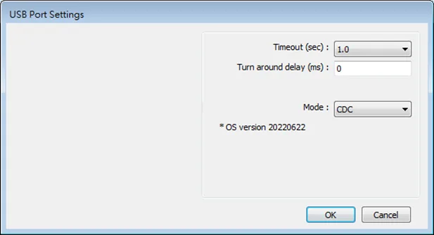
| Setting | Description |
|---|---|
| Timeout (sec) | The barcode scanner is considered as disconnected when the HMI has not received a response from the barcode scanner for a period of time set by timeout. In CDC mode, due to the lack of the terminating character, the timeout setting determines the elapsed time before the HMI stops receiving data. |
| Turn around delay (ms) | The HMI delays the sending of the next command for the specified period of time. |
| Mode | Select CDC or POS mode. |
After adding the barcode scanner in the device list, it can then be selected in object settings with the following addresses to use.
| Address Type | Address Name | Description |
|---|---|---|
| Bit | flag | Indicates the status of data reading. When reading data, the status of flag is set OFF and will return ON after data is successfully read. |
| Word | data | data 0~1999: Store the data read. |
| Word | state | state 0: The value is 0 when no barcode scanner is detected, and the value is 1 when the barcode scanner is connected successfully. |
| Word | len | Len 0: Number of bytes currently read. |