

Bit Lamp
Overview
Bit Lamp object displays the state of a designated bit address. If the bit state is OFF, the State 0 shape will be displayed. If the bit state is ON, the State 1 shape will be displayed.

Configuration
Click [Object] » [Bit Lamp] icon on the toolbar to open a Bit Lamp object property dialog box. Set up the properties, press OK button, and a new Bit Lamp object will be created.
General Tab
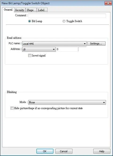
| Setting | Description |
|---|---|
| Comment | User can describe the information of the object. Bit Lamp / Toggle Switch Switch between Bit Lamp and Toggle Switch features. |
| Read address | Click [Setting] to select the [PLC name], [Address], [Device type], [System tag], [Index register] of the bit device that controls the [Bit Lamp] object. Users can also set address in [General] tab while adding a new object. Invert signal Reverses the display of ON / OFF states. For example, if [Invert signal] check box is selected, when the designated bit is OFF, the object displays ON state. |
| Blinking | The appearance of the object may alternate between states when the bit is ON or OFF. Mode: None No blinking Alternating image on state 0 The appearance of the object alternates between State 0 and 1 when the bit is OFF. Alternating image on state 1 The appearance of the object alternates between State 0 and 1 when the bit is ON. Blinking on state 0 The State 0 appearance of the object will blink when the bit is OFF. Blinking on state 1 The State 1 appearance of the object will blink when the bit is ON. Hide picture/shape if no corresponding picture for current state If selected, when there are not enough pictures to represent all the states, hides the picture. Otherwise, displays the last state. |
Note:
- In [Label] tab, if select [ON=OFF (use state 0)] check box, both state 0 and 1 follow the settings of state 0.

Word Lamp
Overview
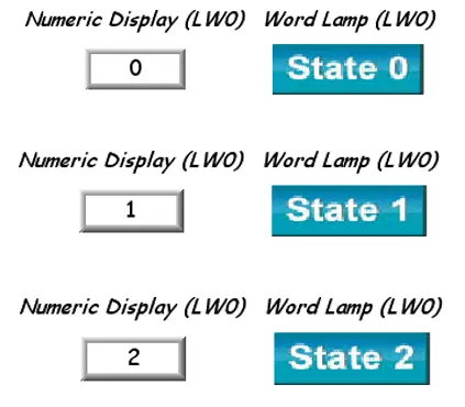
Word Lamp object displays the state according to the value of a designated word register. Up to 256 states are available. When the value of the register is 0, State 0 appearance of the object is displayed, and with the register value being 1 the object displays State 1, and so on.
Configuration
Click [Object] » [Word Lamp] icon on the toolbar to open a Word Lamp object property dialog box. Set up the properties, press OK button, and a new Word Lamp object will be created.
General Tab
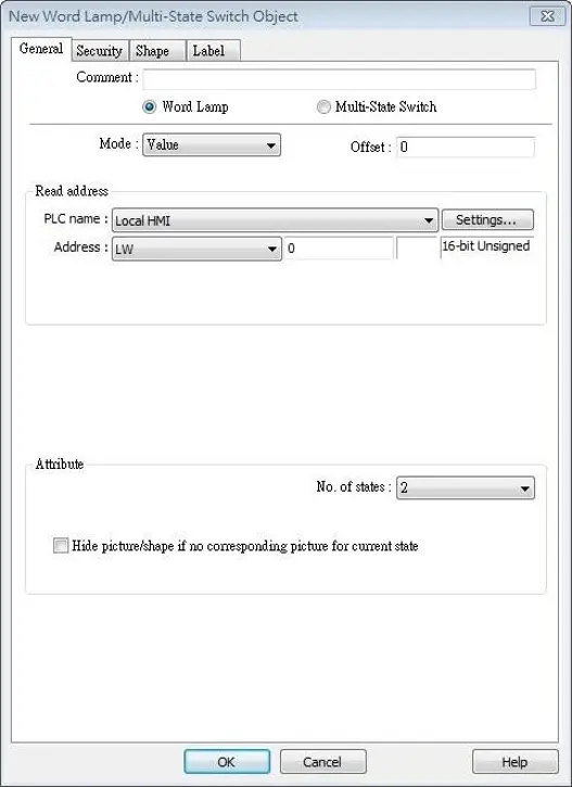
| Setting | Description |
|---|---|
| Comment | User can describe the information of the object. Word Lamp / Multi-State Switch Switch between Word Lamp and Multi-State Switch features. |
| Mode / Offset | Word Lamp object offers the following three modes: Value The state is displayed according to the value in the designated word address and plus the [Offset]. As shown below, if the value within LW-200 is 3, since the offset is set to 3, the shape of state 0 is displayed. (value 3 – offset 3) LSB Convert the value from decimal to binary. The least significant active bit in a binary data word selects the state displayed. 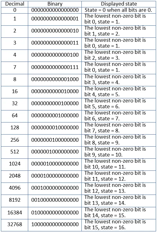 Bit Combination Lamp state depends on the states of bit combinations, where PLC 1 represents the least significant bit (LSB), PLC 2 represents the next LSB, and so on. Maximum number of bit is 4, for a total of 16 states. Changing [No. of states] in Attribute group box changes the number of read addresses. 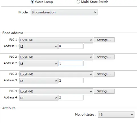 Change state by time The state displayed changes on a time basis. The frequency can be set. |
| Read address | Click [Setting] to select the [PLC name], [Address], [Device type], [System tag], [Index register] of the word device that controls the [Word Lamp] object. Users can also set address in [General] tab while adding a new object. |
| Attribute | No. of states The number of states is utilized by the object. The state is numbered from 0, so the number of states minus 1 will be the state number. If the value within the word register is ≥ [No. of states] defined in Attribute, the highest state will be displayed. If the number of states is set to 8, the valid states will be 0, 1, 2, …, 7. In this case if the word value is 8 or higher, the system will display the state 7 shape. Hide picture/shape if no corresponding picture for current state If selected, when there are not enough pictures to represent all the states, hides the picture. Otherwise, displays the last state. |
Note:
- In [Label] tab, Language 1 determines the relevant settings of the font. For Language 2~8, only the font size can be changed and other settings follow Language 1.
![In [Label] tab, Language 1 determines the relevant settings of the font. For Language 2~8, only the font size can be changed and other settings follow Language 1.](https://media.maplesystems.com/wp-content/uploads/2026/06/wl-label.webp "Word Lamp Label tab")

Set Bit
Overview
The Set Bit object provides two operation modes: manual or automatic. Manual mode can trigger a designated bit address to change the state between ON and OFF when the object is touched. In automatic mode, the bit is automatically activated when a pre-defined condition occurs; touching the button will not be effective.
Configuration
Click [Object] » [Set Bit] icon on the toolbar to open a Set Bit object property dialog box. Set up the properties, press OK button, and a new Set Bit object will be created.
General Tab
| Setting | Description |
|---|---|
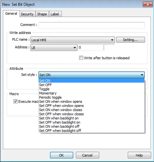
| Write address | Click [Setting] to select the [PLC name], [Address], [Device type], [System tag], [Index register] of the bit device that controls the Set Bit object. Users can also set address in [General] tab while adding a new object. Write after button is released If this function is selected, the action is delayed till button is released; otherwise, the action is executed once the button is pressed. This function does not work with momentary button. |
| Attribute | Set style: Set ON Set ON the designated bit of the device. Set OFF Set OFF the designated bit of the device. Toggle Alternates the bit state each time pressed. Momentary Holds the bit ON only while button is pressed. Periodical toggle Set a designated bit ON and OFF at a set time interval. Time interval can be selected; the range is from 0.1 to 25.5 seconds. Set ON when window opens Set ON the bit within the window when the window opens. Set OFF when window opens Set OFF the bit within the window when the window opens. Set ON when window closes Set ON the bit within the window when the window closes. Set OFF when window closes Set OFF the bit within the window when the window closes. Set ON when backlight on (N/A for cMT-SVR) Set the bit ON when the backlight is turned ON. Set OFF when backlight on (N/A for cMT-SVR) Set the bit OFF when the backlight is turned ON. Set ON when backlight off (N/A for cMT-SVR) Set the bit ON when the backlight is turned OFF. Set OFF when backlight off (N/A for cMT-SVR) Set the bit OFF when the backlight is turned OFF. |
| Macro | Set Bit object can trigger the start of a Macro routine when the Macro has been created in advance. |
| Trigger mode | If [Set style] is set to [Toggle], there is a further selection to make of whether the macro operates after Off to ON, ON to OFF transition, or at both the changes of state. |
Note:
- In [Label] tab, if select [ON=OFF (use state 0)] check box, both state 0 and 1 follow the settings of state 0.
- Using address types other than PLB or PLW_Bit for Set Bit objects with [Periodic Toggle] attribute is not supported by cMT-SVR.
- The Set Style setting in the General tab determines which settings are available in the Security tab. When the Set Style is [Set ON / OFF when window opens], there will be no settings available in the Security tab.
- When [Execute macro] is selected, the sequence in which the object’s write operation and the macro execution is determined by the HMI runtime. In order to exactly arrange the write operation and the macro execution in the desired way, specify the sequence by configuring a Combo Button instead.

Set Word
Overview
The Set Word object provides two operation modes: manual or automatic. Manual mode can change the value in a designated word address when the object is touched. In automatic mode, the word register is automatically activated when a pre-defined condition occurs; touching the button will not be effective.
Configuration
Click [Object] » [Set Word] icon on the toolbar to open a Set Word object property dialog box. Set up the properties, press OK button, and a new Set Word object will be created.
General Tab
| Setting | Description |
|---|---|
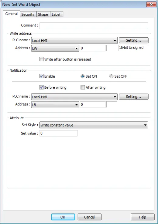
| Write address | Click [Setting] to select the [PLC name], [Address], [Device type], [System tag], [Index register] of the word device that controls the Set Word object. Users can also set address in [General] tab while adding a new object. Write after button is released If this function is selected, the action is delayed till button is released; otherwise, the action is executed once the button is pressed. |
| Notification | If this check box is selected, it will notify a designated bit address (setting ON or OFF). Before writing / After writing Set the state of the designated bit address before or after the manual operation. |
| Attribute | Set Style Select the button action from the drop down list, see Example 2. Dynamic limits Set the [Bottom limit] and [Upper limit] by a designated register, see Example 1. |
Example 1: Dynamic Limits
Set the [Bottom limit] and [Upper limit] by a designated register. When Dynamic Address is LW-n, where n is an arbitrary number, the rule of setting Upper / Bottom limit is:
| Content | 16-bit | 32-bit | 64-bit (cMT / cMT X only) |
|---|---|---|---|
| Dynamic address | LW-n | LW-n | LW-n |
| Bottom limit | LW-n | LW-n | LW-n |
| Upper limit | LW-n+1 | LW-n+2 | LW-n+4 |
When Dynamic Address is LW-100, the rule of setting Upper / Bottom limit is:
| Content | 16-bit | 32-bit | 64-bit (cMT / cMT X only) |
|---|---|---|---|
| Dynamic address | LW-100 | LW-100 | LW-100 |
| Bottom limit | LW-100 | LW-100 | LW-100 |
| Upper limit | LW-101 | LW-102 | LW-104 |
Example 2: Set Style Options
Write Constant Value
Write a preset value. Each time the button is pressed, the value in [Set value] is written to the designated register. Data format is as set by the [Write address] above; it can be 16-bit BCD, 32-bit BCD, …64-bit Double. In the following figure, when the button is pressed, the number 12 is written to the designated register.

Write Constant String (cMT, cMT X Series)
Write a preset string. Each time the button is pressed, the string in [Set string] is written to the designated register. The string format can be: UTF-8, Unicode, Latin-1…etc. In the following figure, when the button is pressed, the string “abcd” is written to the designated register.

Increment Value (JOG+)
Increase value in register by a set amount in [Inc. value], each time when the button is pressed, up to the [Upper limit]. As shown below, each button press increases the value in the register by 1 until the value is 10.

Dercrement Value (JOG-)
Decrease value in register by a set amount in [Dec. value], each time when the button is pressed, down to the [Bottom limit]. As shown below, each button press decreases the value in the register by 1 until the value is 0.

Bounce (up->down->up) (cMT / cMT X Series)
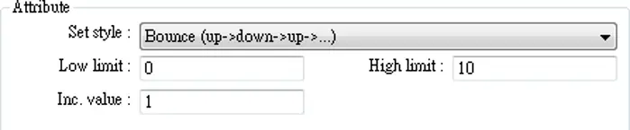
Each time when the button is pressed, the value in the register is increased by the [Inc. value] until the [High limit] is reached, and then the value is decreased by the [Inc. value], each time when the button is pressed, down to the [Low limit]. As shown below, the system will increase the value in the register by 1 each time when the button is pressed, until the value is 10, and then decrease the value by 1 each time when the button is pressed, until the value is 0, and then increase the value again.
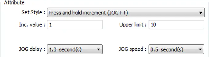
Press and hold increment (JOG++)
When the button is held longer than a set time in [JOG delay], it will increase the value in a register by a set amount :[Inc. value] at a set rate :[JOG speed], to the [Upper limit].
As shown below, when the button is pressed, it increases the value in the designated register by 1. When the button is held longer than 1 second, it increases the value in register by 1 every 0.5 second, till the value is 10.
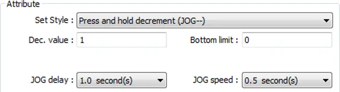
Press and hold decrement (JOG–)
When the button is held longer than a set time in [JOG delay], it will decrease the value in a register by a set amount: [Dec. value] at a set rate: [JOG speed], to the [Bottom limit].
As shown below, when the button is pressed, it decreases the value in the designated register by 1. When the button is held longer than 1 second, it decreases the value in register by 1every 0.5 second, till the value is 0.
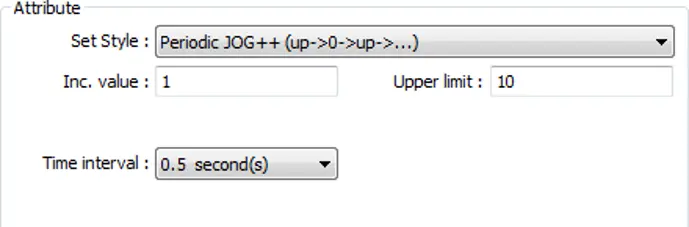
Periodic JOG++
This automatic function increases the value in the register by a set amount: [Inc. value], at a set rate: [Time interval], to the [Upper limit]. As shown below, the system will automatically increase the value in the register by 1 every 0.5 second, till the value is 10. Then the value returns to 0 and add 1 every 0.5 second again.
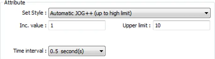
Automatic JOG++
This automatic function increases the value in the register by a set amount: [Inc. value], at a set rate: [Time interval], to the [Upper limit].then holds this value. As shown below, the system will automatically increase the value in the register by 1 every 0.5 second, till the value is 10, and then stop.
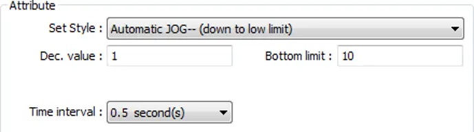
Automatic JOG–
This automatic function decreases the value in the register by a set amount: [Dec. value], at a set rate: [Time interval], to the [Bottom limit].then holds this value. As shown below, the system will automatically increase the value in the register by 1 every 0.5 second, till the value is 10, and then stop.
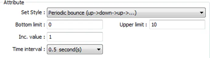
Periodic bounce
Increases the word address value to the [Upper limit] by a [Inc. value] at a set rate in [Time interval], then decreases to the [Bottom limit] by the same value at the same rate. As shown below, the system will increase the value in the designated register by 1 every 0.5 second, till the value is 10, and then decrease the value by 1 every 0.5 second till the value is 0 whenever the screen is active.
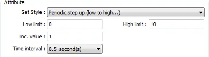
Periodic step up
Step up to the [High limit] by [Inc. value] at a set rate in [Time interval], then reset immediately to the [Low limit]. The action repeats whenever the screen is active. As shown below, the system will increase the value in the designated register by 1 every 0.5 second, till the value is 10, and then reset to 0 and increase again, and the action repeats.
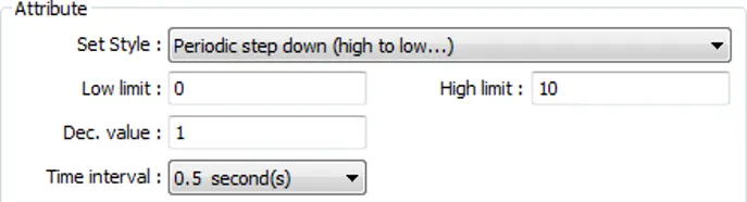
Periodic step down
Step down to the [Low limit] by [Dec. value] at a set rate in [Time interval], then reset immediately to the [High limit]. The action repeats whenever the screen is active. As shown below, the system will decrease the value in the designated register by 1 every 0.5 second, till the value is 0, and then reset to 10 and decrease again, and the action repeats.
Set when window opens / Set when window closes
Automatic function occurs whenever the screen is active. The value entered in [Set value] is set into the word address when the action occurs. If [Set value] is set to 5, when the window opens / closes, the system enters 5 into the designated register.
Set when backlight on / Set when backlight off (Not supported on cMT-SVR)
Automatic function occurs whenever the backlight is active. The value entered in [Set value] is set into the word address when the action occurs. If [Set value] is set to 5, when the backlight turns ON / OFF, the system sets 5 into the designated register.
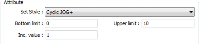
Cyclic JOG+
Each time when the button is pressed, increases the word address value to the [Upper limit] by
[Inc. value] then reset to the [Bottom limit]. As shown below, each time when pressing the button, the system will increase the value in the designated register by 1, till the value is 10, and then reset to 0 and increase again by pressing the button
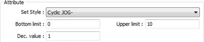
Cyclic JOG-
Each time when the button is pressed, decrease the word address value to the [Bottom limit] by [Dec. value] then reset to the [Upper limit]. As shown below, each time when pressing the button, the system will decrease the value in the designated register by 1, till the value is 0, and then reset to 10 and decrease again by pressing the button.
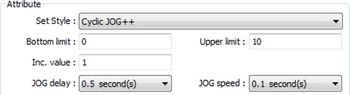
Cyclic JOG++
When the button is held longer than a set time in [JOG delay], it increases the value in a register by a set amount in [Inc. value] at a set rate in [JOG speed], to the [Upper limit], then reset to the [Bottom limit]. As shown below, when the button is held longer than 0.5 second, increase the value in the designated register by 1 every 0.1 second, till the value is 10, and then reset to 0 and increase again by holding the button
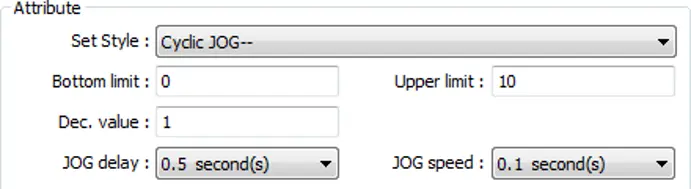
Cyclic JOG- –
When the button is held longer than a set time in [JOG delay], decrease the value in a register by a set amount in [Dec. value] at a set rate in [JOG speed], to the [Bottom limit], then reset to the [Upper limit]. As shown below, when the button is held longer than 0.5 second, decrease the value in the designated register by 1 every 0.1 second, till the value is 0, and then reset to 10 and decrease again by holding the button.
Object Control Command (cMT / cMT X Series)
Listed for selection are commands (with their corresponding command values) available for the control address of various functions. For a given function, with write address set to its control address, Set Word writes the command value and achieves function control.
![Set Word Object Attribute section showing Set Style configured to Object Control Command, with Database Server selected as the Object Type and [1] Start selected as the command.](https://media.maplesystems.com/wp-content/uploads/2026/06/object-control.webp "Object Control Command")
System Tag Command (cMT / cMT X Series)
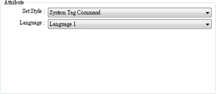
When a system tag is set as write address, for example, LW-9134: Language Mode, the commands relating to the system tag can be selected.
Security Tab
| Setting | Description |
|---|---|
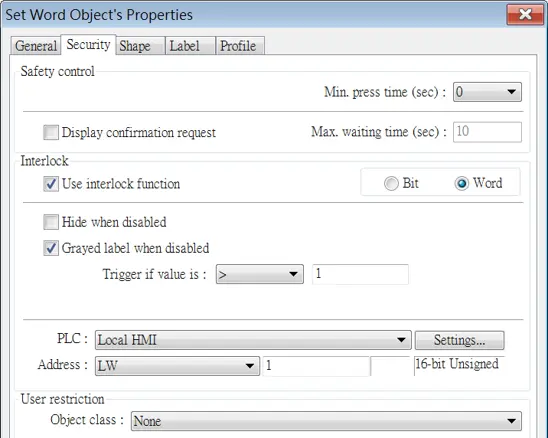
| Interlock | Use interlock function When this option is enabled and [Word] is selected, whether the object is operable depends on the condition of a word address specified in [Trigger if value is:]. In the settings above, the object is operable only when the value in LW-1 is greater than 1. Hide when disabled The object is hidden when the specified condition does not occur in the specified word address. Grayed label when disabled The label of the object turns gray when the specified condition does not occur in the specified word address. Trigger if value is: This setting is for specifying a trigger condition. The available options are: >, <, ==, <>, >=, and <=. A tolerance value can be set for conditions == and <>. For example: 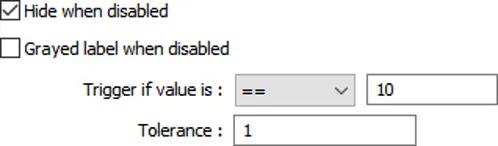 When Hide when disabled is selected, Trigger if value is is set to == 10, and Tolerance is set to 1, the object will be hidden and is not operable when the value in the specified word address is greater than or equal to 11, or smaller than or equal to 9. |
Note:
- Using address types other than PLW for Set Word objects with automatic attributes such as [Periodic set up], [Periodic set down], [Automatic JOG++], [Automatic JOG–], and
- [Periodic JOG++]…etc, is not supported by cMT-SVR.

Toggle Switch
Overview
Toggle Switch object is a combination of Bit Lamp object and Set Bit object. The appearance of the object is controlled by the ON / OFF state of the read bit address. As well, pressing the button sets the value in the bit address according to the settings.
Configuration
Click [Object] » [Toggle Switch] icon on the toolbar to open a Toggle Switch object property dialog. Set up the properties, press OK button, and a new Toggle Switch object will be created.
General Tab
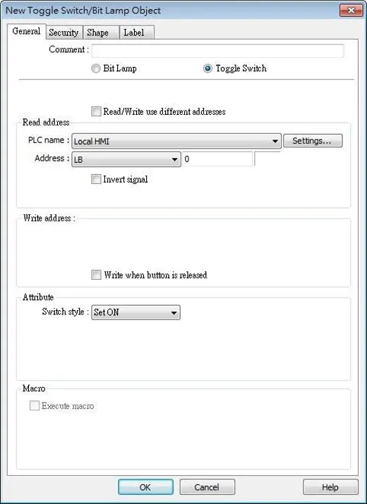
| Setting | Description |
|---|---|
| Comment | User can describe the information of the object. Bit Lamp / Toggle Switch Switch between Bit Lamp and Toggle Switch features. |
| Read/Write use different addresses | Different addresses can be used to read data and write data. |
| Read address | Click [Setting] to select the [PLC name], [Address], [Device type], [System tag], [Index register] of the bit device that controls the [Toggle Switch] object. Users can also set address in [General] tab while adding a new object. Invert signal Reverses the display of ON / OFF states. For example, if [Invert signal] check box is selected, when the designated bit is OFF, the object displays ON state. When [Read/Write use different addresses] option is not selected, the title of this group box will be “Read/Write address”. |
| Write address | Click [Setting] to select the [PLC name], [Address], [Device type], [System tag], [Index register] of the bit device that controls the [Toggle Switch] object. Users can also set address in [General] tab while adding a new object. The address can be the same or different from [Read address]. Write after button is released If this function is selected, the action is delayed till button is released; otherwise, the action is executed once the button is pressed. This function does not work with momentary buttons. |
| Attribute | Set ON – Set ON the designated bit of the device. Set OFF – Set OFF the designated bit of the device. Toggle – Alternates the bit state each time pressed. Momentary – Holds the bit ON only while button is pressed. |
| Macro | Toggle Switch object can trigger the start of a Macro routine when the Macro has been created in advance. |
Note:
- When [Execute macro] is selected, the sequence in which the object’s write operation and the macro execution is determined by the HMI runtime. In order to exactly arrange the write operation and the macro execution in the desired way, specify the sequence by configuring a Combo Button instead.