

Option List
Overview
Option List object displays a list of items that the user can view and select. Once the user selects an item, the corresponding data will be written to a word register.
There are two forms of this object – [List box] and [Drop-down list]. The [List box] lists all items and highlights the selected one. The [Drop-down list] normally displays only the selected item. Once the object is pressed, the system will display a list (which is similar to list box) as shown in the following figure.
![There are two forms of option list object – [List box] and [Drop-down list]. The [List box] lists all items and highlights the selected one. The [Drop-down list] normally displays only the selected item.](https://media.maplesystems.com/wp-content/uploads/2026/06/list-options.webp "List Box and Drop-Down styles")
Configuration
Click [Object] » [Option List] icon on the toolbar to open an Option List object property dialog box. Set up the properties, press OK button, and a new Option List object will be created.
Option List Tab
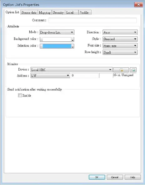
| Setting | Description |
|---|---|
| Attribute | Mode: The list style, either [List box] or [Drop-down list]. Background color: Set the background color. Selection color: Set the background color for the selected item. Direction: With the [Auto] option selected, the Option List expands based on its vertical alignment with the window’s centerline as the reference. If the Option List is positioned above the centerline, its menu content expands downwards; conversely, if it’s positioned below the centerline, the menu content expands upwards. With the [Down] option selected, the Option List will consistently expand downwards. Conversely, with the [Up] option selected, the Option List will consistently expand upwards. 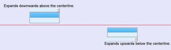 Please note that if the object is positioned near the window’s edge and the option to expand towards the edge is selected, the menu content display will be compressed. Style: This option is available only when the selected mode is [Drop-down list]. Available styles are [Standard] and [Classic]. The appearance of the objects will be shown in cMT / cMT X style when [Standard] is selected, and shown in iE/eMT/XE style when [Classic] is selected. When the project is converted from iE/eMT/XE to cMT / cMT X, the default style will be [Classic]. Font size: When [Same size as label] is selected, the font size set in Label tab will be used for the drop-down list. When [Fixed size] is selected, the system default font size will be used for the drop-down list. Row height: Set the row height for the drop-down list. |
| Monitor address | The corresponding value of the selected item will be written to [Monitor address]. Write when button is released If this check box is selected, the selected item value will be written to [Monitor address] after the button is released. |
| Send notification after writing successfully | Set On/Off the designated bit address after successfully writing data to PLC. |
Note:
- The [write when button is released] option is not available on cMT / cMT X Series models.
Source Data Tab
There are several options for the Source of item data: predefine, dates of historical data, item address and User Account.
Predefine
The list is manually defined in [Mapping] tab.
The number of items can be adjusted by [Item no.], and each item represents one state. Each item has a corresponding value which will be written to [Monitor address].
Dates of historical data
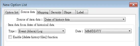
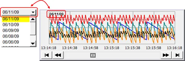
Option List object can be used with historical data display objects, such as Trend Display object, History Data Display object and Event Display object to control which history file should be shown. The figure below is an example of Option List used with Trend Display.
| Setting | Description |
|---|---|
| Type | Two options are available: [Event (Alarm) log] and [Data sampling]. |
| Date | Set the date format. YYYY means a four digits year (EX: 2012), YY means a two digits year (EX: 12), MM means month and DD means day. |
| Data Sampling | Select which Data Sampling object is displayed when [Type] is [Data Sampling], and it should be the same as the [Data sampling object index] configured in [Trend Display] or [History Data Display]. |
| Enable [delete history data] function | If selected, a control address can be set. Writing “1” to this address will delete the history data of the specified date. |
Notes:
- In [Dates of historical data] mode, since the system automatically reads the historical data and finds the date information, it is not necessary to configure in the [Mapping] tab.
- The error message displayed in Option List can be modified in [Mapping] tab.
Item Address
The list will be read from the given [Item address] and controlled by [Control address]. The following options will be available:

| Setting | Description |
|---|---|
| Control | [Address]: If the value at this address is changed to 1, the option list would be replaced by items defined at [Item address]. After updating, the value will be restored to 0. [Address + 1]: Define the number of items in [Item address]. |
| Item | Assign the item address. UNICODE The item will use UNICODE characters, such as Chinese characters. The length of each item Define the number of letters for each item, the unit is Word. |
Notes:
- The UNICODE characters used here should be used by Text object, so that EasyBuilder Pro will compile the needed fonts and download these fonts to HMI, then the UNICODE letters can be correctly displayed.
- [The number of items] multiplied by [The Length of each item] must be less than 4096 words.
- In [Item address] mode, the system automatically disables the settings in [Mapping] tab.
- After changing windows, the item address content will be removed. To retain it, use “Set when window opens” setting of Set Word object for automatic content update.
User Account
If [Enhanced Security] mode is enabled, [User account] would appear in the [Source of item data] and it lists the names of users.
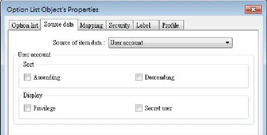
| Setting | Description |
|---|---|
| Sort | Select the sorting method from [Ascending] or [Descending]. |
| Display | If [Privilege] is selected, the privileges for each user will be displayed in option list. If [Secret user] is selected, even though it is defined to be hidden in [System parameter settings] » [Security] » [Enhanced Security], the users will still be displayed in [Option List]. |
Notes:
- The address that controls user index is [Control Address +2 (LW-n+2)] which is set in [System Parameters] » [Security] » [Enhanced Security].
- The [Privilege] option is not available on cMT / cMT X Series models.
Mapping Tab
This table displays all available states/items, their item data and values. To change the number of available items, please go to [Option list tab] » [Attribute] » [Item no.].
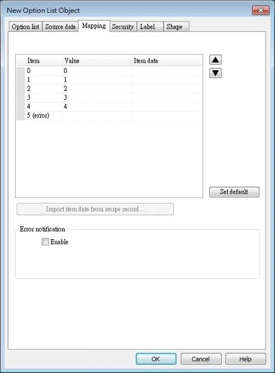
| Setting | Description |
|---|---|
| Item | The system lists all available items. Each item represents a state that will be displayed in the list. This field is read-only. |
| Value | Here user can assign value for each item, basing on the following two criteria: For reading: If the value in [Monitor address] is changed, the object selects the first-matched item. If no item is matched, the status goes to error state and signals the notification bit register (if requested). For writing: The system writes this value to [Monitor address] when user selects an item. |
| Item data | Text displayed for each item. The Option List object displays the text of all items in the list for users to review and select. |
| Import item data from recipe record | This feature is enabled when select [Recipe-Selection] as [Monitor address]. Click [Import item data from recipe record] to open the [Records of Recipe Database] setting dialog box. Select [Item data source], the data belonging to the selected column will all be imported to Option List object.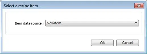 Before importing, the number of items in Option List changes according to the number of items defined in [Records of Recipe Database]. After importing, modifying Records of Recipe Database will not change the content of Option List. |
| Error state | On error state, the list box removes the highlight to represent no item is selected and the drop-down list displays the data of error state. Only the drop-down list uses error state, list box is not able to use error state. For example, item number 8 is the error state when specifying 8 in [Item no.]. (The first item number is 0.) |
| Set default | Reset all values or states to default. That is, set 0 for item 0, 1 for item 1, and so on. |
| Error notification | The system will set ON/OFF to the specified bit register when error is detected. The signal of the bit register could be used to trigger a procedure for correcting the error by using objects such as Event Log, Alarm Bar, or pop-up window. |

PLC Control Object
Overview
PLC Control object can execute commands when it is triggered.
Configuration
Click [Object] » [PLC Control] icon on the toolbar to open the PLC Control Object management dialog box. To add a PLC Control object, click [New], set up the properties, press OK button and a new PLC Control object will be created.
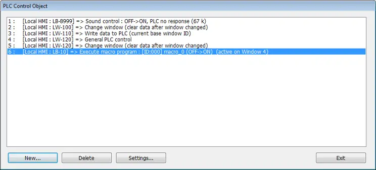
Click [New] and the following dialog box appears:
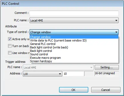
Notes:
- The [General PLC Control] option is not available for cMT / cMT X Series.
- Triggering [Screen hardcopy] in cMT Viewer will result in files being saved into the USB
- disk / SD card connected to the cMT / cMT X HMI. Likewise, the [Back light control] option in cMT Viewer will control the backlight of the HMI itself.
- Selecting [Change window] or [General PLC Control] as [Type of control] will require more than one trigger word (consecutive). Using a user-defined tag PLC will require declaring an array datatype.
Types of Control
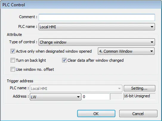
Change Window
| Setting | Description |
|---|---|
| Active only when designated window opened | Allow this operation only if a particular screen is displayed. |
| Turn on back light | The backlight is turned ON when the window is changed. |
| Clear data after window changed | Reset the value at trigger address to zero when the window object is changed. If [Use window no. offset] is selected, this option will only show when a negative offset is used. |
| Use window no. offset | Select the check box and select a window offset, the new window no. to change to will be the value in [Trigger address] plus the offset. For example, if [Trigger address] is LW-0 and offset is set to -10. When the value in LW-0 is 25, the system will change to window no. 15 (25-10=15). The range of the offset is -1024 to 1024. |
Note:
- If [LB-9017] is set ON, the write-back function will be disabled, the new window number is not written back into a designated address.
Place a valid window number in the designated trigger address to change the base screen to the new window number. The new window number is written back into the designated address.
For example, if current window is window no. 10, and [Trigger address] is set to LW-0, When LW-0 is changed to 11, the system will change the current window to window no. 11, and then write 11 to LW-1.
When the window is changed, the new window number is written back into the address that is calculated by [Trigger address] and the data format, as shown in following table.
| Data Format | Trigger address | Write address |
|---|---|---|
| 16-bit BCD | Address | Address + 1 |
| 32-bit BCD | Address | Address + 2 |
| 16-bit Unsigned | Address | Address + 1 |
| 16-bit Signed | Address | Address + 1 |
| 32-bit Unsigned | Address | Address + 2 |
| 32-bit Signed | Address | Address + 2 |
| 64-bit Unsigned | Address | Address + 4 |
| 64-bit Signed | Address | Address + 4 |
Write Data to PLC (current base window)
Each time the base window is changed, the new window number will be written into the [Trigger address]. If [Use window no. offset] is selected, the window number of the base window plus the window number offset will be written into the [Trigger address].
General PLC Control (Legacy HMIs only)
Transfer word data blocks from PLC to HMI, and vise-versa, and the transfer direction is controlled by the value in the [Trigger address].
| Value in [Trigger Address] | Action |
|---|---|
| 1 | Transfer data from PLC register > HMI RW register |
| 2 | Transfer data from PLC register > HMI LW register |
| 3 | Transfer data from HMI RW register > PLC register |
| 4 | Transfer data from HMI LW register > PLC register |
Four consecutive word registers are used as described in the following table:
| Address | Purpose | Description |
|---|---|---|
| [Trigger address] | Determine the direction of data transfer | The valid values are listed in the above table. When a new control code is written into the register, HMI will start to transfer. After data transfer is finished, the value will be set to 0. |
| [Trigger address] +1 | The size of data to transfer. | The unit is word. |
| [Trigger address] +2 | Offset to the start address of PLC register | Assume the value is “n”, where n is an arbitrary number, the start address of PLC register is [Trigger address + 4 + n]. Take an OMRON PLC as an example:If [Trigger address] uses DM-100, [Trigger address + 2] will be DM-102. If the value in DM-102 is 5, the start address of data source would be DM-109 (100 + 4 + 5 = 109). |
| [Trigger address] +3 | Offset to the start address of LW or RW memory in HMI | Take OMRON PLC as an example:If set [Trigger address] to DM-100, [Trigger address + 3] will be DM-103. If the value in DM-103 is 100, the start address of memory in HMI is RW-100 or LW-100. |
Example:
To use PLC Control object to transfer 16 words data in OMRON PLC, starting from address DM-100, to the HMI address, starting from RW-200. The setting is shown below:
- Firstly, create a PLC Control object, set [Type of control] to [General PLC control], and set [Trigger address] to DM-10, that is, to use the four sequential registers start from DM-10 to control data transfer.
- Confirm the data size and the offset addresses.
- Set DM-11 to 16, since the number of words to transfer is 16 words.
- Set DM-12 to 86, which indicates the address of data source is DM-100 (100=10+4+86).
- Set DM-13 to 200, which indicates the destination address is RW-200.
- Set DM-10 according to the direction of data transfer.
- If set DM-10 to 1, the data will be transferred from PLC to HMI RW register,
- If set DM-10 to 3, the data will be transferred from HMI RW register to PLC.
Back light control (write back)
When [Trigger address] is turned ON, HMI backlight will be turned ON/OFF and [Trigger address] will be turned OFF. Any touch on the screen will turn the backlight on.
Back light control
When [Trigger address] is turned ON, HMI backlight will turn ON/OFF and the state of [Trigger address] will not be changed.
Sound control
When the state of the designated [Trigger address] changes, the HMI will play the sound selected from the sound library. There is a further selection determines whether the sound is played after Off to ON, ON to OFF transition, or at both of the changes of state.
Execute macro program
Select a pre-defined Macro from the drop-down list. When the state of the designated [Trigger address] changes, the selected Macro is executed.
There is a further selection determines whether the Macro is executed after Off to ON, ON to OFF transition, or at both of the changes of state. If select [Always active when ON], the macro will be executed repeatedly. (The shortest time interval between runs is 0.5 second.)
Screen hardcopy
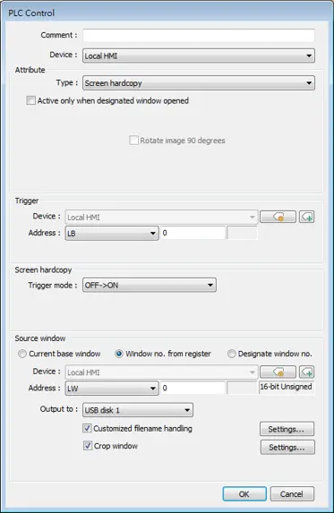
When the state of the designated [Trigger address] changes, print the selected screen. If select [SD card] or [USB disk] as [Printer], a “hardcopy” folder will be generated in the selected external device for saving the printed screen in JPG format. The name of the JPG files starts from yyyymmdd_0000.
To print the screen using a printer, go to System Parameter Settings » Model tab and set the printer.
To print the screen using a remote printer, go to System Parameter Settings » Printer/Backup Server tab and configure the parameters.
There are three options to specify the source window for hardcopy:
- Current base window
- Print the base window currently opened
- Window no. from register
- Print the window designated by the value in a designated word address.
- Designate window no.
- Directly select a window to be printed.
Customized File Handling
This feature can be used to customize naming of the folders and the JPG files.
| Setting | Description |
|---|---|
| Folder name | The folder name can be an alphanumeric name, and certain half-width symbols are allowed: !@#$%^&_+{}~;:,. The folder name can also be specified by a naming syntax. Dynamic format The folder names can be set by a designated word address, or by a naming syntax indicating the current system time. The syntax can be specified by selecting time buttons or entering the syntax in Format field. The length limit is from 1 to 25. Note: Up to 10 layers of folders can be created. The exceeding layers will be ignored. |
| File name | The way to specify a file name is similar to specifying a folder name. Note: If the file name already exists, the system will add “_0001” to the file name as a serial number. The numbers of the later files add up until “_9999”. The files after “_9999” will be ignored. For example, if the three file names exist: “A.jpg”, “A_0001.jpg”, “A_0003.jpg”. When trigger screen hardcopy with the same file name, the coming files will be named in this order: “A_0002.jpg”, “A_0004.jpg”, “A_0005.jpg”, and so on. |
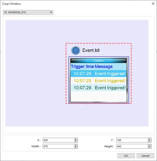
Crop window
With this option selected, taking a cropped screenshot is possible.
Notes:
- A background printing procedure is performed when the printed window is not the current base window.
- If the hard-copied window is a background window, its [Direct Window] and [Indirect Window] objects will not be printed.
- When using a dynamic format name, the system will use a “_” sign as a substitute for invalid symbols.
- When using a dynamic format name, if screen hardcopy is triggered without specifying the format first, the system will save the file in the default directory, which is: hardcopy\yymmdd_0000.JPG
- On cMT / cMT X models, a triggered bit address is reset to its original state automatically, whereas on eMT/iP/iE/mTV models, the state of a triggered bit address is retained.

Direct Window Object
Overview
Direct Window object opens or closes a pop-up window assigned by a designated bit register.
When the state of the bit register changes, the pop-up window appears at the predefined location. The display area for the pop-up window is limited by the size of predefined location. Returning the state of the bit register closes the pop-up window.
The difference between Direct Window and Indirect Window is that Direct Window is controlled by a bit register, while Indirect Window is controlled by a word register.
Configuration
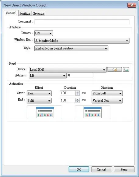
Click [Object] » [Embed Window] » [Direct Window] icon on the toolbar to open a Direct Window object property dialog box. Set up the properties, press OK button, and a new Direct Window object will be created.
General Tab
| Setting | Description |
|---|---|
| Style | This setting is available only on cMT / cMT X Series. When a base window contains an underlay window, this setting determines the display style of a Direct Window placed in the underlay window. Embedded in parent window The Direct Window is displayed in its parent window. When a Direct Window is placed in an underlay window, the Direct Window is displayed in the underlay window when it is called in the base window. Popup window The Direct Window is displayed in the base window. When a Direct Window is placed in an underlay window, the Direct Window is displayed in the base window when it is called in the base window. Title Bar Setting When [Enable title bar] is selected, a field shows for entering the caption in the title bar. The caption can be selected from Label Tag Library. 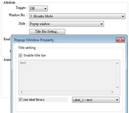 |
| Read address | Click [Setting] to select the [PLC name], [Address], [Device type], [System tag], [Index register] of the bit device that controls the pop-up window. Users can also set address in [General] tab while adding a new object. |
| Attribute | Style Set the display style of the pop-up window. There are two styles: • No title bar The pop-up window has no title bar and cannot be dragged. 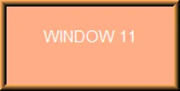 • With title bar The pop-up window has a title bar that can be dragged to move the window. 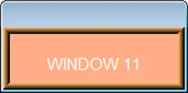 Window no. Set the pop-up window number. |
| Animation (cMT / cMT X Series) | Effect Different effects may be used for Start (window appears) and End (window disappears). Available effects: • Fade • Fly • Float • Wipe • Split • Circle • Clock • Zoom • Turn • Push Duration Specifies how many milliseconds (ms) a transition effect takes to complete. Direction The direction of the transition. |
Position Tab
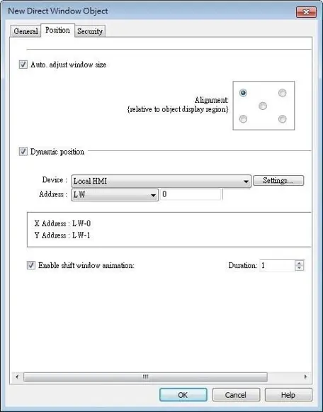
| Setting | Description |
|---|---|
| Auto. adjust window size | Automatically resizes the Direct Window and align the pop-up window to the preset region. Alignment Sets a reference point of the pop-up window from one of the five positions on the screen; for example, if the lower-right region is selected, the lower-right corner of the pop-up window is aligned to the lower-right region of the Direct Window. See Example 1. |
| Dynamic position | With this option selected, the position of the window on the screen can be changed dynamically by the values in the designated address. Enable shift window animation With this option selected, the window changes position with transition effect. |
Direct Window Object Example
Create window no. 11 which can be controlled by a Toggle Switch with address LB-0.
- Create a Direct Window object and set read address to LB-0.
- In this example, the reference point for alignment is set to the lower-right region.
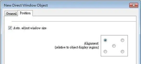
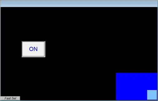
- When LB-0’s state is ON, window no. 11 will show:
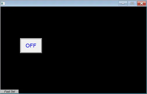
- When LB-0’s state is OFF, window no. 11 will be hidden.
Notes:
- For Legacy HMI models, a screen can display up to 24 pop-up windows simultaneous including System Message Window, Direct Window and Indirect Window. For cMT / cMT X Series, the number of pop-up windows is not limited.
- The system does not allow opening the same window with two Direct (or Indirect) Windows in one base window.
- If the pop up window has monopoly property enabled, then when the window pops up, all background windows may not be operated until the monopolizing window has been closed.

Indirect Window Object
Overview
Indirect Window object opens or closes a pop-up window assigned by a designated word register. There are two ways to use Indirect Window object: The first is to use the profile of Indirect Window object, and let the pop-up window be resized and displayed in the defined profile; the second is to automatically resize the window according to the size of the pop-up window to be displayed. To close the pop-up window, assign 0 to the designated word register.
The difference between Direct Window and Indirect Window is that Direct Window is controlled by a bit register, while Indirect Window is controlled by a word register.
Configuration
Click [Object] » [Embed Window] » [Indirect Window] icon on the toolbar to open the object property dialog box. Set up the properties, press OK button, and a new Indirect Window object will be created.
General Tab
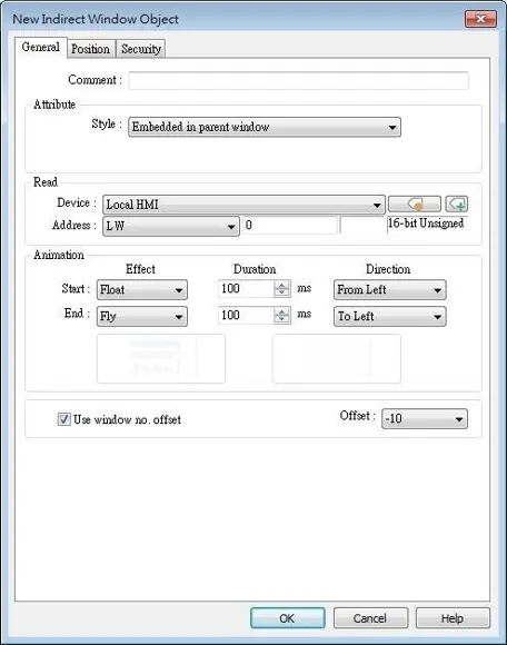
| Setting | Description |
|---|---|
| Style | This setting is available only on cMT / cMT X Series. When a base window contains an underlay window, this setting determines the display style of an Indirect Window placed in the underlay window. Embedded in parent window The Indirect Window is displayed in its parent window. When an Indirect Window is placed in an underlay window, the Indirect Window is displayed in the underlay window when it is called in the base window. Popup window The Indirect Window is displayed in the base window. When an Indirect Window is placed in an underlay window, the Indirect Window is displayed in the base window when it is called in the base window. Title Bar Setting When [Enable title bar] is selected, a field shows for entering the caption in the title bar. The caption can be selected from Label Tag Library. ![When [Enable title bar] is selected, a field shows for entering the caption in the title bar. The caption can be selected from Label Tag Library, if desired](https://media.maplesystems.com/wp-content/uploads/2026/06/indirect-titlebar.webp) |
| Read address | Click [Setting] to select the [PLC name], [Address], [Device type], [System tag], [Index register] of the bit device that controls the pop-up window. Users can also set address in [General] tab while adding a new object. |
| Attribute | Style Set the display style of the pop-up window. There are two styles: • No title bar The pop-up window has no title bar and cannot be dragged. • With title bar The pop-up window has a title bar that can be dragged to move the window. Window no. Set the pop-up window number. |
| Animation (cMT / cMT X Series) | Effect Different effects may be used for Start (window appears) and End (window disappears). Available effects: • Fade • Fly • Float • Wipe • Split • Circle • Clock • Zoom • Turn • Push Duration Specifies how many milliseconds (ms) a transition effect takes to complete. Direction The direction of the transition. |
| Use window no. offset | Sets the offset of the window number for selecting the pop-up window. The window number of the pop-up window is calculated by the value in the word register added to the offset. For example, assume the value in the register is 20 and offset is 5, the pop-up window number will be 25. |
Position Tab
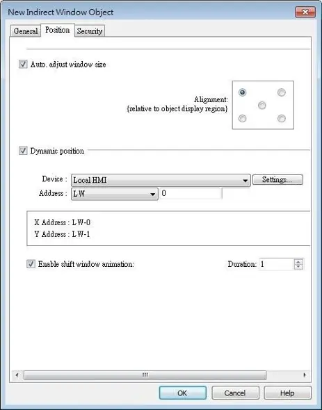
| Setting | Description |
|---|---|
| Auto. adjust window size | Automatically resizes the Indirect Window and align the pop-up window to the preset region. Alignment Sets a reference point of the pop-up window from one of the five positions on the screen; for example, if the lower-right region is selected, the lower-right corner of the pop-up window is aligned to the lower-right region of the Indirect Window. See Example 1. |
| Dynamic position | With this option selected, the position of the window on the screen can be changed dynamically by the values in the designated address. Enable shift window animation With this option selected, the window changes position with transition effect. |
Indirect Window Object Examples
Implementing an Indirect Window
Here is an example of using Indirect Window. The setting is shown in the following figure, set the address to LW-0 which assigns the window number. Create window no. 11 and 12 first.
Instructions: Implementing an Indirect Window
Create a new Indirect Window Object
Create an Indirect Window object, set address to LW-0, and select [Auto. adjust window size].Create Window 11 and Window 12 in your project before creating an indirect window object. You cannot reference windows that do not yet exist.Select Positional Alignment
Select the region where the window is to be displayed.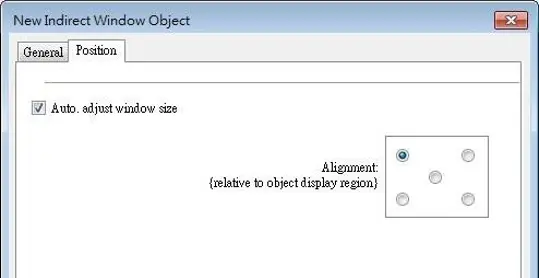
Enter Values in LW-0 to control the indirect window
Enter value 11 in LW-0, the pop-up window displayed is window no. 11.
Enter value 12 in LW-0, the pop-up window displayed is window no. 12.
Enter value 0 in LW-0, the pop-up window is closed.
To close the pop-up window, apart from entering 0 in the designated word register, another way is to place a Function Key object in the pop-up window, and set the key to [Close window].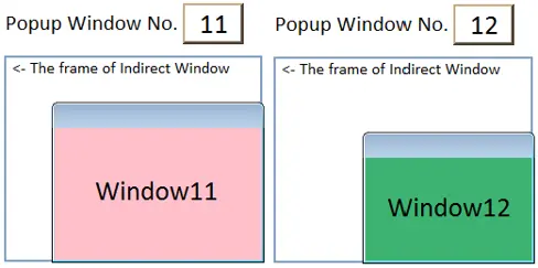
Indirect Window Styles
Here is an example showing the difference between these two styles: [Embedded in parent window] and [Popup window]. The style setting determines how an Indirect Window placed in an underlay window is displayed when it is called in the base window.
Instructions: Indirect Window Styles
Add Windows and configure underlay
Add two base windows: Window no. 10 and Window no. 11. Add an underlay window in Window no. 10 and set Window no. 11 as the underlay window.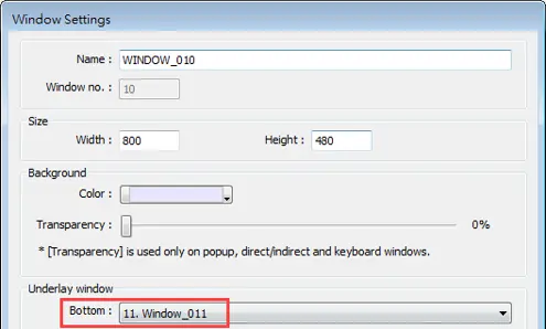
Create several objects in Window 10
In our picture, we have three toggle switch objects created. The objects themselves do not matter as we are simply using them to view the difference in wondow styles.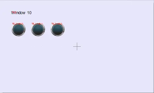
Create an Indirect Window and Numeric
In Window no. 11 create an Indirect Window object and a Numeric Input object. Set both read addresses to LW-0.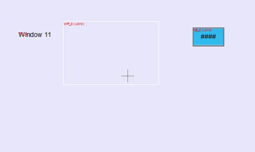
Indirect Window Result: Embedded in Parent Window style
By entering a window number in the Numeric Input object, the Indirect Window is displayed according to the selected style.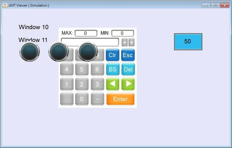
Indirect Window Result: Popup window style
By entering a window number in the Numeric Input object, the Indirect Window is displayed according to the selected style.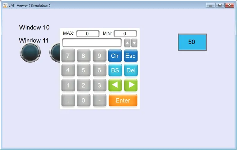
Notes:
- For legacy HMI models, a screen can display up to 24 pop-up windows simultaneous including System Message Window, Direct Window and Indirect Window. For cMT / cMT X Series, the number of pop-up windows is not limited.
- The system does not allow opening the same window with two Direct (or Indirect) windows in one base window.
- If the pop up window has monopoly property enabled, then when the window pops up, all background windows may not be operated until the monopolizing window has been closed.