Before setting up a CODESYS project to communicate with an iR-ECAT module, it is assumed that the development PC running CODESYS and the cMT device running the CODESYS runtime are connected via Ethernet, and the cMT device is connected to the iR-ECAT module using the EtherCAT Protocol. For information on how to wire the iR-ECAT, please see the installation guide pinout diagrams for the cMT device in use, as well as the installation guide and user manual for the iR-ECAT on DIP switch settings and wiring.
Connect iR-ECAT to CODESYS
Follow these steps to connect an iR-ECAT product to CODESYS
Add Device
Right click on Device (Weintek Built-in CODESYS) and select Add Device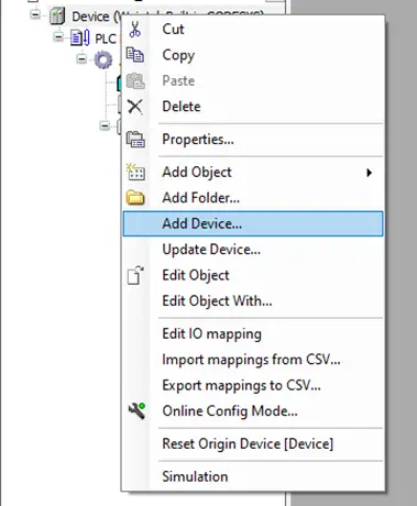
Add EtherCAT Master
In the Add Device window, check the Display all versions checkbox and then select FieldBusses -> EtherCAT -> Master -> EtherCAT Master Version 3.5.10.0 and click Add Device: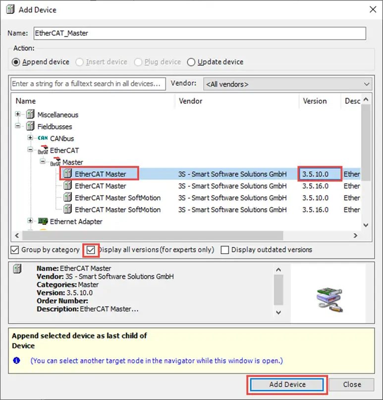
Select “Device” from the newly added EtherCAT Master to add the iR-ECAT slave device
Select the newly added EtherCAT Master device, and then in the Add Device window, select Fieldbusses -> EtherCAT -> Slave -> Weintek Labs., Inc. – Coupler -> iR-ECAT and click Add Device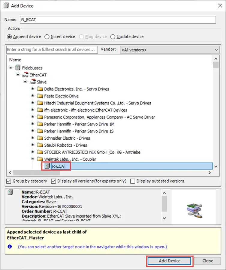
Set the Gateway address for the EtherCAT interface (MAC address)
Double click on the newly added EtherCAT Master device to open the settings. In the General settings tab, click the Source Address (MAC) Browse button to set the gateway address to use for the EtherCAT interface.This should match the MAC address of the cMT-X device’s CODESYS LAN port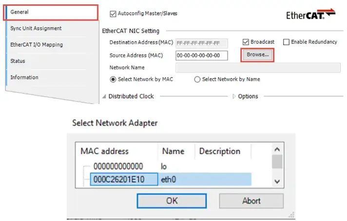
Set the Node IDs
Double click on the iR_ECAT device to open the device settings. In the General tab, check the Enable Expert Settings checkbox. In the Identification section, select the Configured Station Alias radio button, and for the value field, enter the node ID set on the X1 and X10 dip switches on your iR-ECAT device.These may be set to any ID except 00 00. Our example is set to 00 01.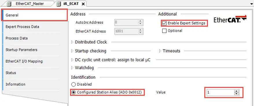
Add all attached I/O modules (Method A: Scan for Devices)
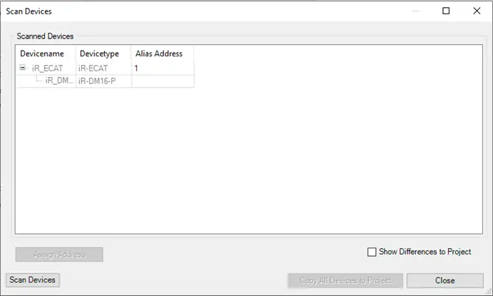
Right click the EtherCAT Master device and click Scan For Devices.If the gateway for the EtherCAT Master device is set up, and the PC is able to login to the CODESYS device, this will automatically scan the connected iR-ECAT module and find all attached IO modules, allowing them to be added all at once.
In this example, only a DM16-P is connected.
Add all attached I/O modules (Method B: Manually)
Right click the iR_ECAT device and click Add Device. In the Add Device window, select Fieldbusses -> EtherCAT -> Module and then add each connected IO module in the order they are connected to the base module.Once again, in this example only a DM16-P is connected.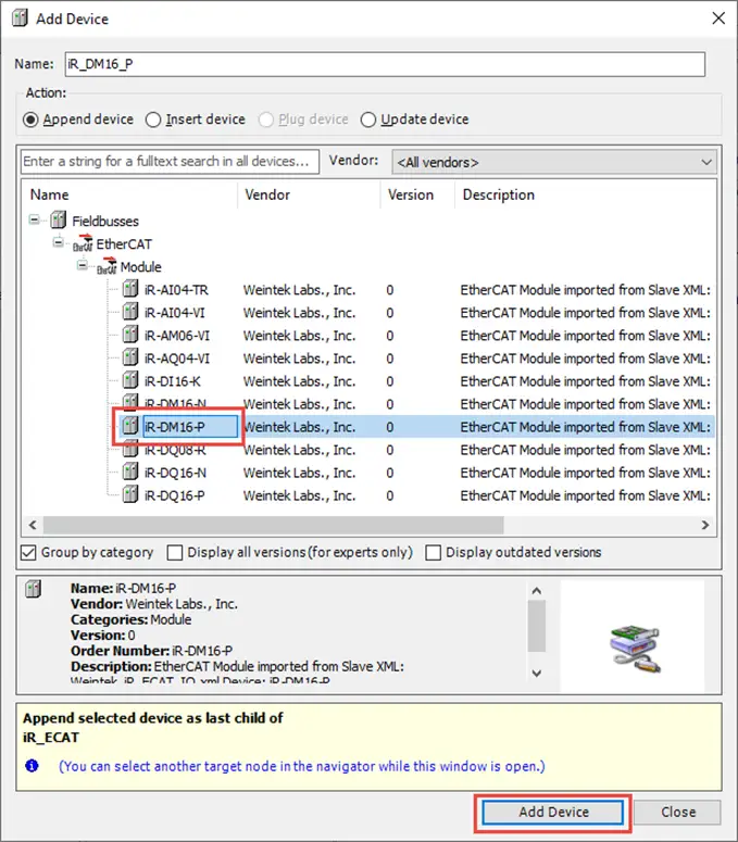
Add Variables in the PLC_PRG Program
Add variables in the PLC_PRG program to channel to the connected IO.In this example, we will simply add one Boolean for each IO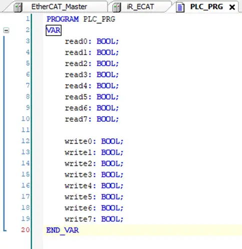
Map the variables to the I/O
Double click in the iR_ECAT device and go to the EtherCAT I/O Mapping tab. There, map the newly created variables to the IO connected.In this example, we only have an iR-DM16-P connected, so we will connect our 8 read and write variables to the input and output bits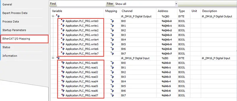
Ensure variables are set to update automatically
While in the EtherCAT I/O Mapping tab of the iR_ECAT device, set the Always update variables to Enabled 2 (always in bus cycle task):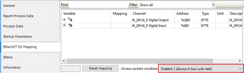
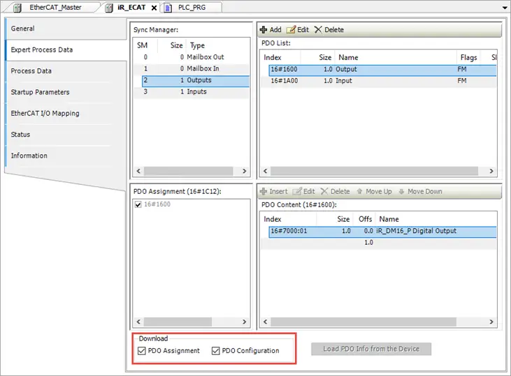
Enable PD0 Assignment and Configuration boxes
Finally, in the iR_ECAT device settings, go to the Expert Process Data tab and check the PDO Assignment and PDO Configuration checkboxes in the Download section