Before setting up a CODESYS project to communicate with an iR-ETN module, it is assumed that the development PC running CODESYS, the cMT device running the CODESYS runtime, and the iR-ETN module have all been connected via Ethernet and are on the same IP subnet. If this is not the case, the devices will be unable to communicate.
Connect iR-ETN to CODESYS
Follow these steps to connect an iR-ETN product to CODESYS.
Add Device
Right click on Device (Weintek Built-in CODESYS) and select Add Device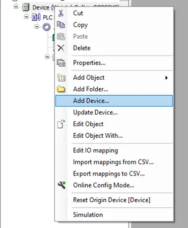
Add an Ethernet Adapter
In the Add Device window, select Fieldbuses -> Ethernet Adapter -> Ethernet version 3.5.10 and click Add DeviceThe iR-ETN is an Ethernet based device, so you’re selecting it via device type, not specific model number.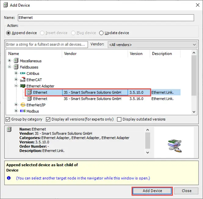
Select ‘Device’ from the newly added Ethernet Adapter
Right click on the newly added Ethernet adapter and select Add Device: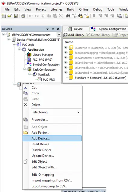
Choose MODBUS TCP Master
Select Fieldbuses -> Modbus -> Modbus TCP Master -> Modbus TCP Master and click Add DeviceAs the iR-ETN uses the MODBUS TCP Protocol, the CODESYS project needs to identify it by the protocol.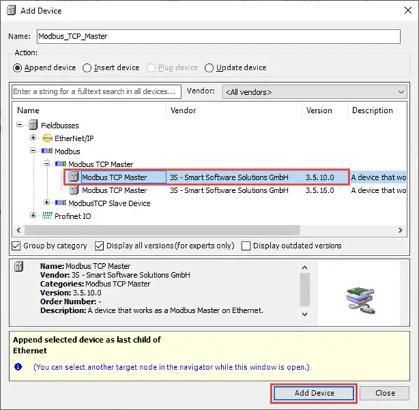
Add a MODBUS TCP Slave device, nested under the Master device created in the previous step
Select the new Modbus TCP Master device, then select Fieldbuses -> Modbus -> Modbus TCP Slave -> Modbus TCP Slave and click Add Device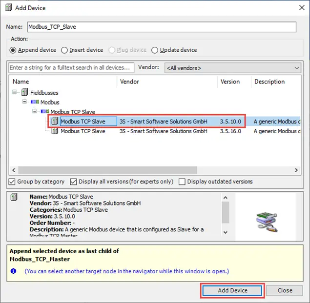
Enter the IP Address
Double click the newly added Ethernet adapter to open the Ethernet device configuration. In the General tab, enter the IP address and Subnet mask to match your iR-ETN’s configurationThis is the Ethernet Adapter, the first device that was added (the iR-ETN itself).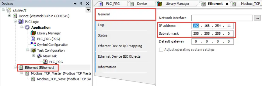
Enable Auto Reconnect of MODBUS TCP Device
Double click the Modbus TCP Master device and navigate to the ModbusTCPMasterParameters tab and set AutoReconnect to TRUE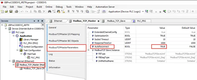
Select the network interface corresponding to the iR-ETN IP.
With CODESYS connected to the base device, i.e. Device (Weintek Built-in CODESYS), click […] in the Ethernet device General tab and select the Network interface corresponding to the Ethernet device’s IP address![click […] in the Ethernet device General tab and select the Network interface corresponding to the Ethernet device’s IP address](https://media.maplesystems.com/wp-content/uploads/2026/04/image-2026-04-01T104531.383.webp "iR-ETN 7")
Change ‘Unit ID’ of MODBUS TCP Slave Device
Double click on the Modbus TCP Slave device and go to the ModbusTCPSlave Parameters tab. There, change the Unit-ID Parameter to match the Unit ID on the iR-ETN module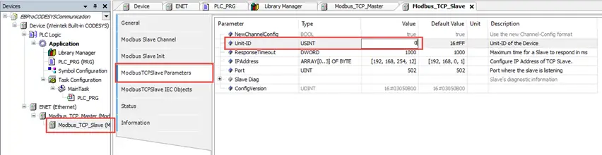
Add a tag to the MODBUS Device
To add a tag to the Modbus device, go to the Modbus Slave Channel tab and click Add Channel to open the Modbus Channel window. Select the access type to match the data type of the tag.In this case, a bool-type tag is being added, so the Read Discrete Input type is used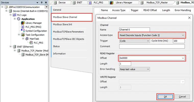
Add the same tag to the CODESYS program
Double click on PLC_PRG in the Devices pane and add a Boolean tag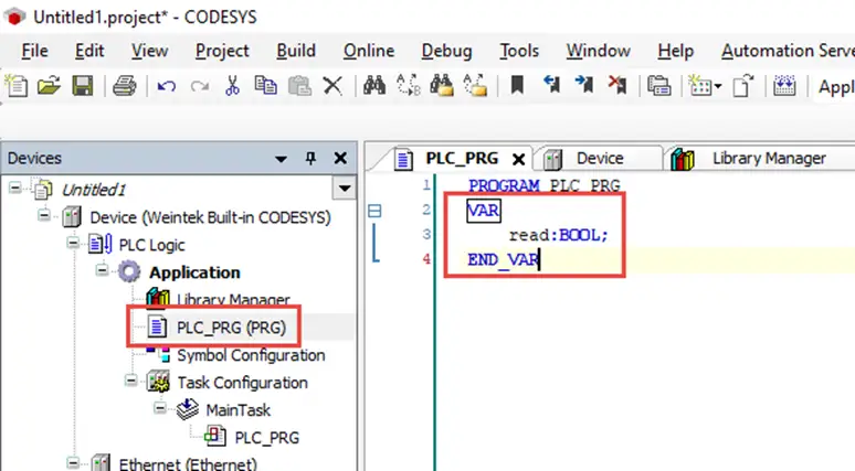
Connect the tag references
With the tag added, double click on the Modbus TCP Slave device once more, go to the ModbusTCPSlave I/O Mapping tab, expand the Variable tree entirely and click the […] button to connect it to the new read Boolean tag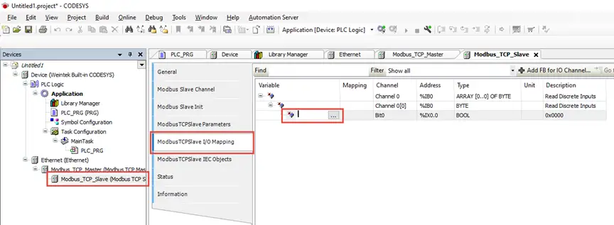
Attach the tag
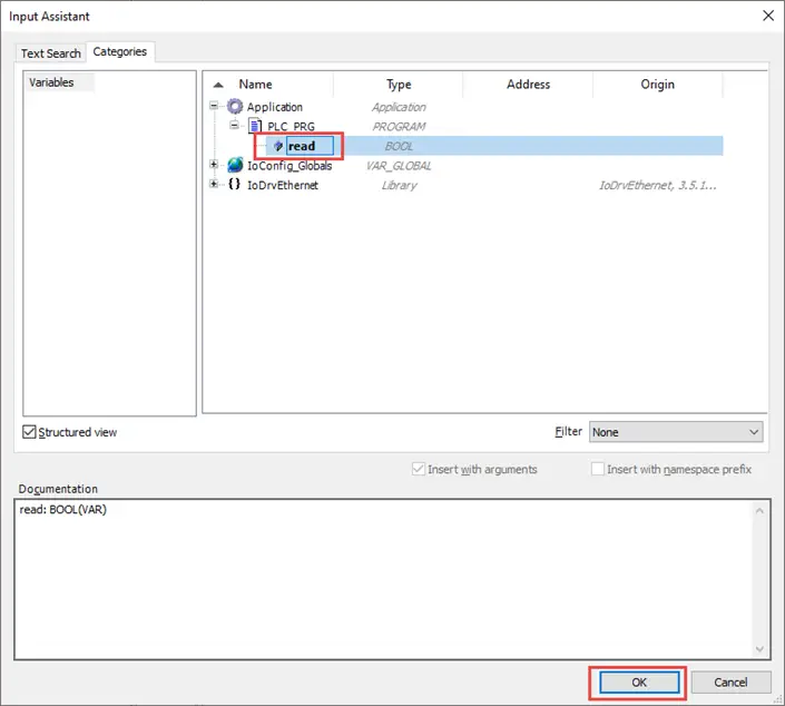
In the Input Assistant window, select Application -> PLC_PRG -> read to attach the read Bool tag to the Modbus channel created prior.