
Overview & Concepts
Wi-Fi capability in EasyBuilder Pro allows supported HMIs to connect to a wireless network instead of using a wired Ethernet connection. By connecting the HMI to a Wi-Fi access point, the device can communicate with PLCs, servers, and other network resources without requiring a physical network cable. This provides greater flexibility for system installation and allows the HMI to participate in network-based communication features.
Some Maple Systems HMI units have Wi-Fi connectivity built in (cMT-SVR-200 Headless, for example) while others use a simple module (M02) that plugs directly into the rear of the HMI.
Once connected to a wireless network, the HMI functions similarly to a device connected through Ethernet. It can exchange data with controllers, access remote services, and support network-based features within the project.
Common uses of Wi-Fi connectivity include:
- Connecting HMIs to plant networks where Ethernet cabling is impractical
- Enabling remote monitoring tools such as cMT Viewer, WebView, or VNC
- Allowing communication with PLCs, databases, or cloud services over the network
By supporting wireless connectivity, Wi-Fi-capable HMIs provide additional flexibility for installation, maintenance, and remote access while maintaining the same network communication capabilities used in wired configurations.
Implementation
Setup via Web Interface
Implementing Wireless connectivity for HMIs is not a matter of adding objects or changing your project settings – it’s about the hardware itself. Headless HMIs such as the cMT-SVR-200, cMT-SVR-202 have a single Ethernet port and a built-in Wi-Fi connection.
Wi-Fi configuration is done within the System Settings of the unit. But to get there, you need to connect to it from a development PC.
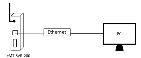
To configure the wireless connection of the HMI via a web browser, connect the HMI to a PC with RJ-45 crossover Ethernet cable as the diagram shown below.
On the PC, right-click on Ethernet adapter of the PC and select Properties. You can set your PC to static IP mode from [Internet Protocol Version 4 TCP/IP V4] » [General] tab. Select “Use the following IP address” and set up an IP address.
This IP address must be unique and non-conflicting. If this is the HMI’s initial setup, please set the IP address to 169.254.0.X, where X is any number between 2 and 254, and set the subnet mask to 255.255.255.0.
How to know the IP address of the cMT HMI
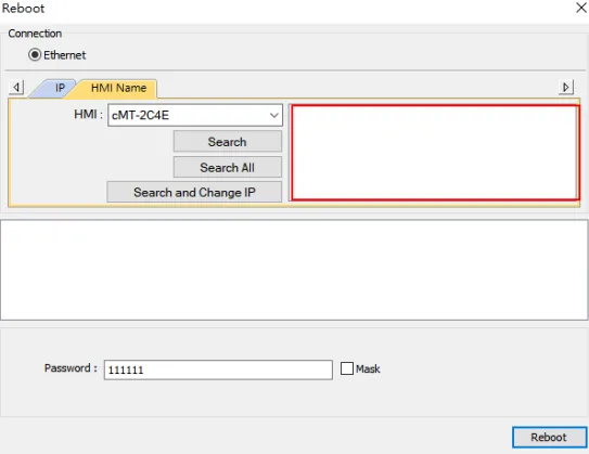
Launch Utility Manager » Select [cMT Series] at the top-left corner. Go to [Analysis & Testing] tab » [Reboot]
![Launch Utility Manager » Select [cMT Series] at the top-left corner. Go to [Analysis & Testing] tab » [Reboot]](https://media.maplesystems.com/wp-content/uploads/2026/04/image-664.webp "Reboot button in the Analysis and Testing tab of Utility Manager")
On the [HMI Name] tab, click on [Search All]. The IP address of the cMT-SVR-200 will be displayed on the right box. Then close this window.
How to Setup Wireless Connection
Open a web browser (IE, Chrome, or Firefox) and enter the IP address of the HMI. Select [System setting] and enter its password. The default password is 111111.
![Once you know the cMT unit's IP, Open a web browser (IE, Chrome, or Firefox) and enter the IP address of the HMI. Select [System setting] and enter its password. The default password is 111111.](https://media.maplesystems.com/wp-content/uploads/2026/04/image-666.webp "Enter the IP of the HMI in a browser")
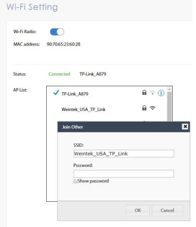
On [Wi-Fi] tab, enable [Wi-Fi Radio]. Click on an access point from the AP List. The popup window will prompt you to enter its password. Once the wireless connection succeeds, the status will display
“Connected.”
![On [Wi-Fi] tab, enable [Wi-Fi Radio]. Click on an access point from the AP List. The popup window will prompt you to enter its password. Once the wireless connection succeeds, the status will display
“Connected.”](https://media.maplesystems.com/wp-content/uploads/2026/04/image-667.webp "Wi-Fi Tab, enable the Wi-Fi radio")
[Join other SSID]- You can manually connect the HMI to an access point that is not displayed on the AP list. Make sure the Wi-Fi signal is strong enough.
![[Join other SSID]- You can manually connect the HMI to an access point that is not displayed on the AP list. Make sure the Wi-Fi signal is strong enough.](https://media.maplesystems.com/wp-content/uploads/2026/04/image-668.webp "Clicking Join Other allows you to manually input an SSID")
| Name | Descriptions |
|---|---|
| Wi-Fi Radio | Turn Wi-Fi radio ON or OFF. |
| Status | It shows one of the statuses including Stopped, Connecting, Retrying, or Connected. |
| AP List | A list of currently available access points. |
| Refresh icon | It can refresh the Access Points list. |
| Join other(SSID) | It allows users to manually add an access point and connect with. |
| SSID | SSID name of the wireless access point to connect with. |
| Password | Enter the password. The password can either be visible or invisible when entering the password. |
| Connect/Disconnect | Connect or disconnect from a wireless router. |
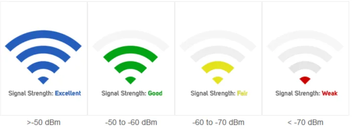
The signal strength is classified into four levels: Excellent, Good, Fair, and Weak, as shown below. (Using System register LW-11402(16bit))
How to Switch Access Point to Others
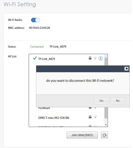
Click on the current wireless connection. Choose Yes on the popup window to disconnect the connection
Select another access point and enter its password
How to set Static IP
Setting to static IP is available. To use the static IP address, click the blue information icon. Choose [Usevstatic IP address below] and enter the IP address, mask, gateway IP, and DNS.
![Setting to static IP is available. To use the static IP address, click the blue information icon. Choose [Use static IP address below] and enter the IP address, mask, gateway IP, and DNS.](https://media.maplesystems.com/wp-content/uploads/2026/04/image-673.webp "Click info icon and select Use Static IP to give the unit a static IP address")
Setup of M02 Module
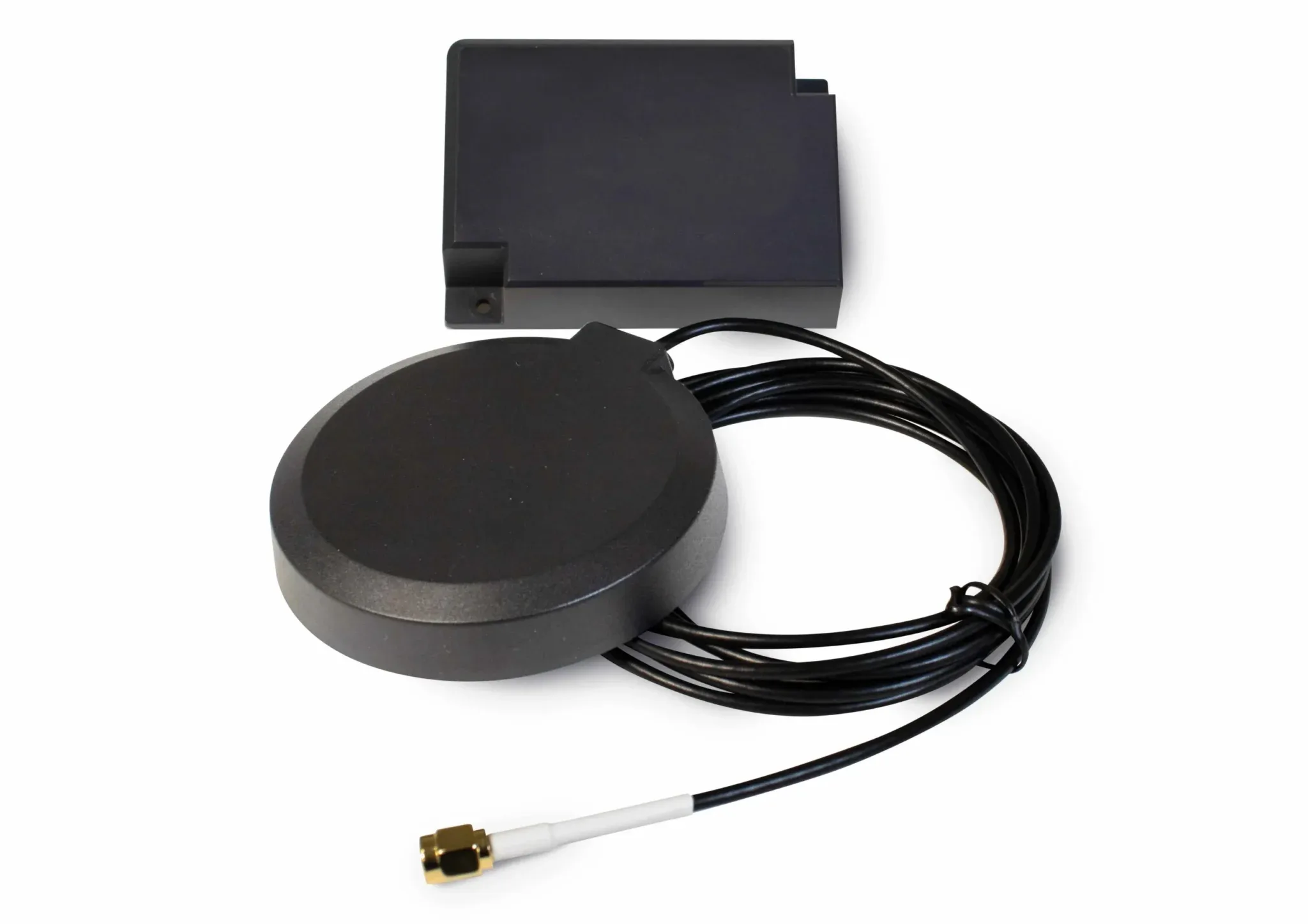
Select cMT models with 10″ display screens have the ability to install an M02 Wi-Fi module, which adds Wi-Fi connectivity to the existing dual Ethernet options offered on cMT and cMT X Series HMIs.
The M02 Module
Module Installation
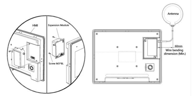
Connect the Module: Insert the module into the designated slot on the rear cover of the HMI.
Secure the Module: Use two M3*8L screws to tighten the module firmly to the rear cover of the
HMI. Ensure that the module is mechanically secured to the HMI using the threaded screws at the
rear cover.
Connect the Antenna: Lock the SMA connector of the antenna securely to the connector on the
module. Be sure to reserve adequate space for the antenna installation, taking into consideration
the minimum bend radius to prevent physical damage and maintain optimal performance. The
antenna must be completely enclosed within the final product.
Module Configuration – HMI System Settings Menu
Use the System Setting Menu from the HMI to configure the M02 Wi-Fi Module.
Instructions: Module Configuration – HMI System Settings Menu
Install the M02 Module
Install the M02 Module to the rear of the HMI unit and secure the screws, then apply power to the HMIAccess Wi-Fi Settings
Tap the button on HMI to access the Network tab and locate the [WiFi Connection] settings.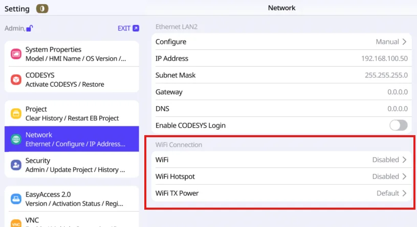
Find an Access Point to which you want to connect
Choose an Access Point (AP), enter the password, and tap [Connect].Optional: Adjust the power setting to Enhanced if connection status is weak
Adjust the [WiFi TX Power] setting to either Default or Enhanced power as needed.
Module Configuration – Web Browser
Connect the HMI to your PC and use the PC’s Web Browser to configure the M02 Wi-Fi Module.
Instructions: Module Configuration – Web Browser
Install the M02 Module
Install the M02 Module to the rear of the HMI unit and secure the screws, then apply power to the HMIConnect the HMI to your PC
Connect the HMI to a PC with an Ethernet cable.Enter HMI’s IP address to access the Settings menu.
Open a browser and enter the HMI’s IP address to access its settings.Enable the Wi-Fi
Navigate to the Network tab and select [WiFi].Find an Access Point to which you want to connect
Choose an Access Point (AP), enter the password, and click [OK]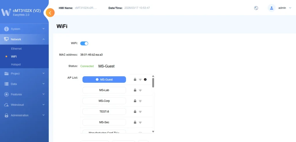
Wi-Fi System Registers
The following System Register addresses are reserved for the Wi-Fi Operation of an HMI.
| Register No. | Descriptions | Associated object | Readable/Writable |
|---|---|---|---|
| LW-11383 (16bit) | Wi-Fi control (1:Disconnected, 2:Connect, 3:Popup Wi-Fi setting dialog) | Multi-State Switch | R/W |
| LW-11384 (16bit) | Error code (0:No error, 1:No such device, 2:Wi-Fi radio is off) | Word Lamp | R |
| LW-11385 (16bit) | Status (0:Stopped, 1:Connecting, 2:Retrying, 3:Connected) | Word Lamp | R |
| LW-11386 (16 words) | Connected SSID | ASCII | R |
| LW-11402 (16bit) | Signal strength level (0:None, 1:Weak, 2:Fair, 3:Good, 4:Excellent) *Note 1 | Word Lamp | R |
| LW-11403 (16bit) | Country code *Note 2 | ASCII | R/W |
| LW-11404 (16bit) | Wi-Fi radio (0:Off, 1:On) | Multi-State Switch | R/W |
*Note 1: The signal strength is classified into four levels: 1. Weak (<-70 dBm), 2. Fair (-60 ~ -70 dBm), 3. Good (-50 ~ -60 dBm), 4. Excellent (>-50 dBm).
*Note 2: Enter Wi-Fi country code in ASCII for uppercase letters, the setting will take effect after rebooting HMI. Wireless regulations vary from country to country. The country code selection affects the list of channels of the wireless radio.